DDDAC Power Supply (background and tweaks)
Introduction
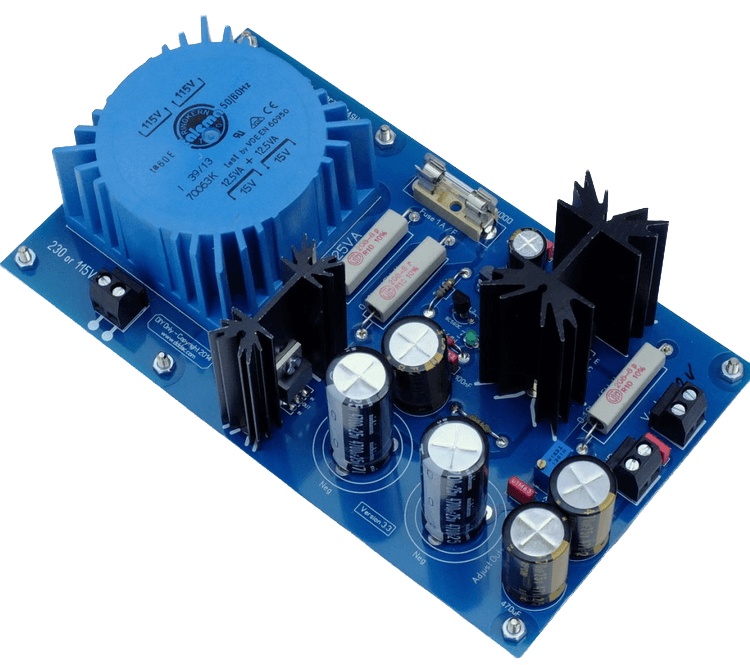
Here you see the well known DDDAC Power supply. I designed it to go together with the DDAC1794 kits, Of course it can also be use for many other audio applications.
As DDDAC kit it comes as “5V” or “12V” version. As it is adjustable, the range is a bit wider than that actually.
The kit is laid out to be a 1A max power supply. But is that really the max you can get out of this? And… are there other tweaks? How does this PSU actually work? Often heard: can I make a 2A or 3A PSU out of it?
This blog will try to answer those questions and will give some good guidance of the electronic background and deliver a few tweaks for everyone who wants to beef it up or experiment with the sound quality….
This is how it basically works:
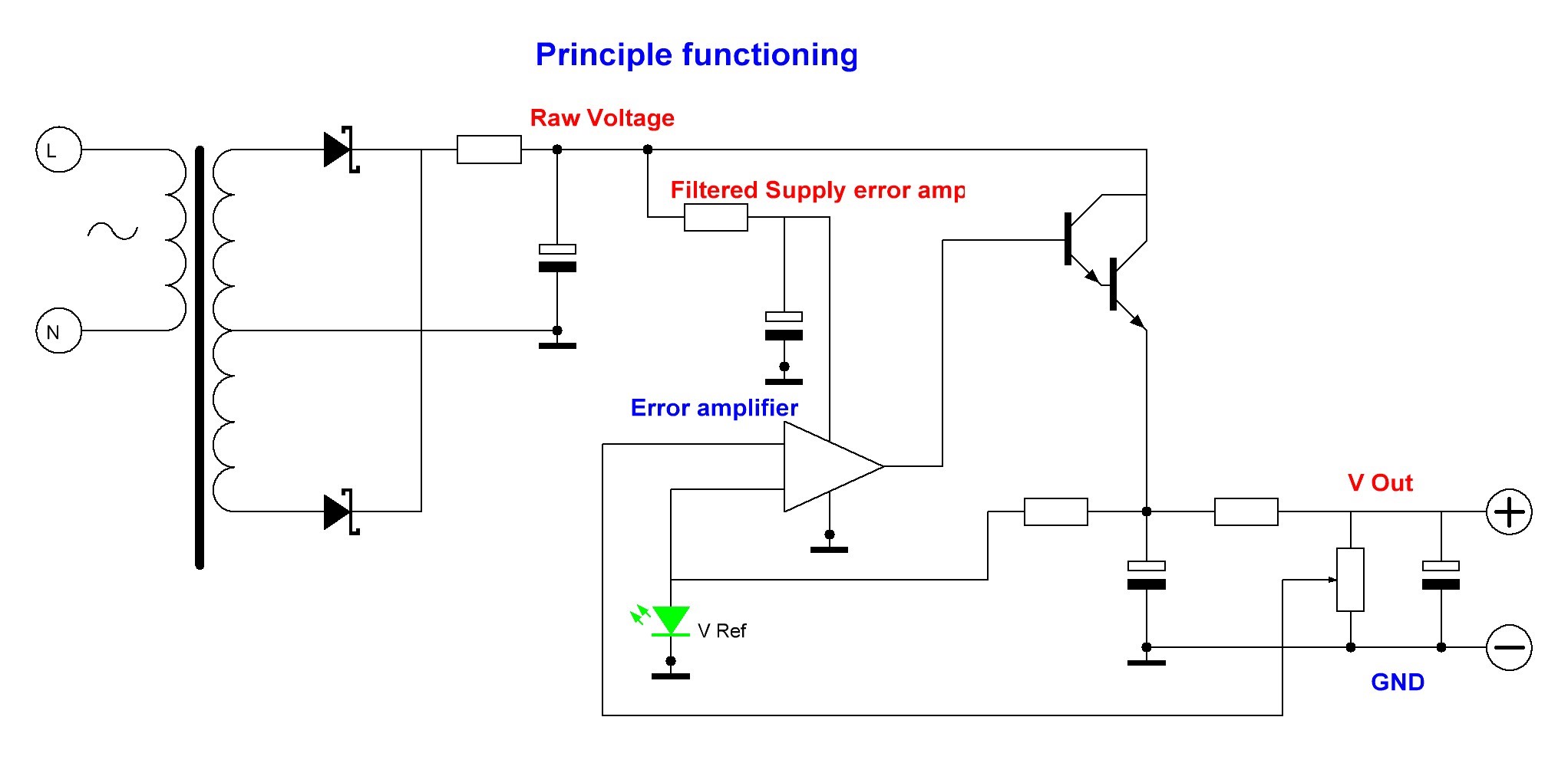
As you can see, it is a simple principle without rocket science. I use full wave rectifying with schottky diodes. After that comes the filter to make a raw DC voltage out of it with some ripple on top (which is a sawtooth 100Hz, which has nasty harmonics). Here is a simplified RC rectifying filter shown. In reality it is a “RCRC” filter, but later on I will show a “RCRLC” solution which does more filtering.
To arrive at the desired output voltage, there is a discrete error amplifier which compares the output voltage with a voltage reference (the green diode) and drives the output darlington. Key here is to also filter the supply voltage for the error amplifier. As any ripple and noise left over will find its way, even when attenuated, into the output.
The error amplifier in detail:
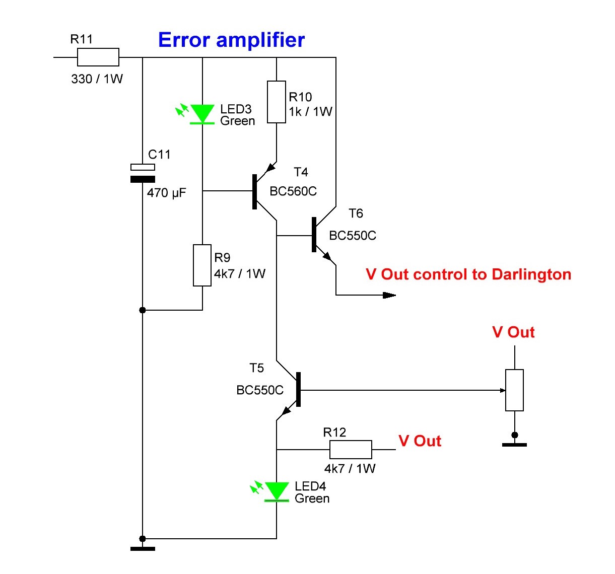
The supply voltage for this stage is filtered by R11 (330 Ohm) and C11 (470uF). This will result in a 1Hz corner frequency. Resulting in a -40dB pre-ripple rejection at the 100Hz first harmonic. An extra benefit is that this supply DC voltage does not have the larger saw tooth. For example at full load the RAW DC ripple can be peak tot peak 1 Volt or so. In the error amplifier this will be only 10mV. The supply current is roughly 5mA so you loose 1,5 volt here. This is a compromise between amount of filtering and losing voltage control headroom – later more on this – You can also increase C11 but somehow I could not measure a huge impact. Nice is the slow start of the PSU by doing this. But I leave it with 470uF to be honest.
The actual error amplifier is T5 and drives T6 which in turn drives the output darlington with low impedance (emitter follower). T4 with the green LED is a current source, to maximize the gain of the error amplifier. All very straight forward and this setup results in a ripple and noise rejection (PSRR) of roughly -71dB over a bandwidth of 500kHz, which is a pretty good figure 🙂
Complete circuit with all values:

Maybe you noticed. Just through the backdoor, I introduced the first tweak…. Replacing the second RC rectifier filter section with a resistor and an inductor for additional ripple and noise filtering. Just by the way, mentioning, I supply this level of detail for your DIY purpose only. A ~ 1:1 copy for commercial use is prohibited. (that includes changing R11 to for example 270 Ohm 😉 ). If you are interested in any DDDAC design in your OEM product, just contact me.
Later on more on the choke / coil / inductor (what is it really?)
Let’s start tweaking
(and measuring)
Impact of transformer size on headroom and power output
I guess this is the most requested tweak. How can I beef up the PSU to deliver more power? First you need to understand what the minimum required headroom of the PSU is…. Meaning what RAW DC input voltage do I need to still have a regulated output?
Good question: let’s calculate and MEASURE it 🙂
But first look at the design….. If you start with your desired output voltage. Let say 12,5 Volt for example. To be able to actually arrive at this you could work your way “up” throught the circuit:
- V-drop darlington (1,5V)
- V-drop T6 (0,7V)
- V-drop Vce T4+R10 (??V)
- V-drop Filter R11 (1,5V)
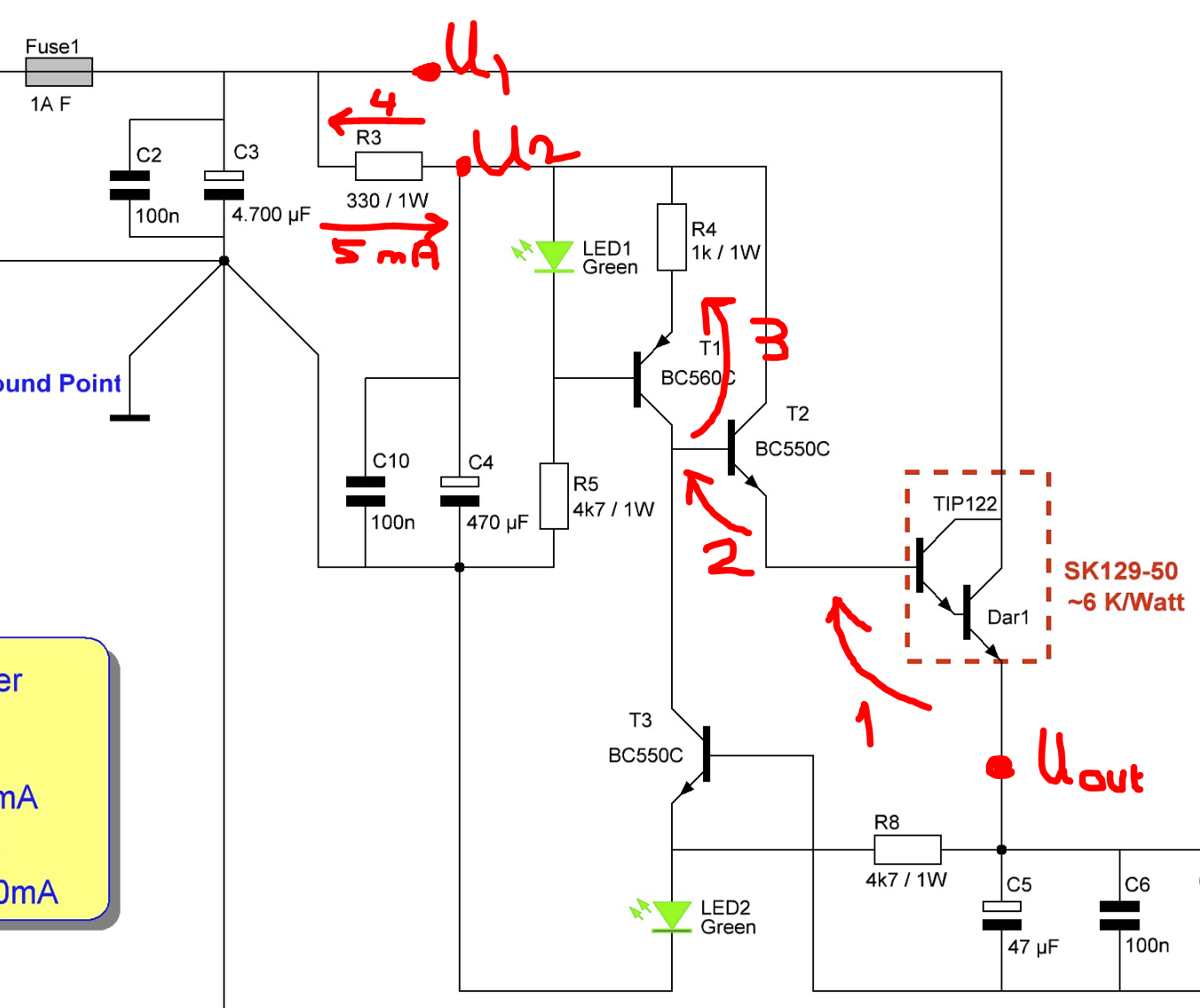
So this adds up to 3,7 Volt + Vce (T4) and R10. The last one is a bit variable depending on the load and control, but lets say ~ 1,3 Volt. In order for T4 to NOT saturate (the error amplifier will lose all gain and stop rejecting ripple…) you need at least 0,5 V to be at the safe side. With low load and hence high RAW DC Voltage, this is where the headroom sticks and it varies between say 5 volts and saturation in overload conditions.
In conclusion: 3,7 +1,3 +0,5 is 5,5 Volt – So we wanted in our example 12,5 Volt, so we need a minimum DC input (= average DC level of rectified and filter voltage) of 12,5 + 5,5 = ~18 Volt….
Do we have that available in the standard version?
Now transformers all behave the same: at no load they are having a much higher AC voltage output. This can range from 10 to 30% easily. On the other hand the secondary windings will have a loss in their Ohm Resistance of the winding. And … at this point everything will collapse… using the transformer above its VA power rating, the core will saturate and the voltage will drop rapidly. (and the transformer will heat up and burn out eventually)
I hope it make sense when I state that using a transformer way below it specs will keep the raw DV voltage more constant.
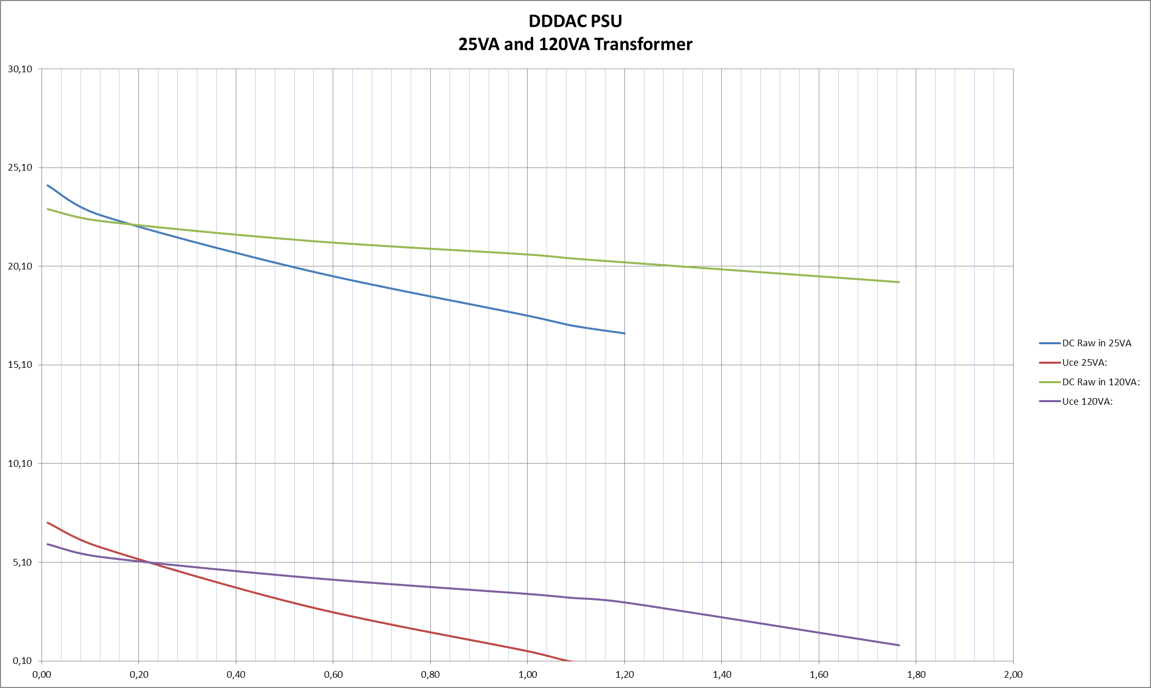
At the left you see measurements of the DDDAC PSU with the standard 25VA blue Talema transformer versus a RKT 120VA version
The top lines show clearly what I just described and also that indeed 1A is the absolute max you draw from the standard version. The bottom line shows the Vce over the current source. At 0,1 Volt it will saturate. Oh, that means with the RKT transformer you can go up to easily 2A? Yes that works fine… May be you ask, why not a transformer with higher AC voltage? Yes, will work of course but then you will dissipate much more power in the TIP122 output darlington. Can be done, but read further below what to do…
Before I forget… I indeed could confirm by measurement of the PSRR which dropped sharply from ~-70dB to -40dB when the delta between input voltage and output voltage becomes less than ~5,6 Volt…
Power Dissipation…
The most important point in increasing the output power capabilities is the TIP122 power loss dissipation and the resulting heatsink dimensions….
So assume we use the 120VA (still 2x15Vac) and load the 12,5V PSU with 2A. We now have (measured) ~7 Volt delta. In the darlington we need to dissipate 2A x 7V = 14 watt – for the TIP122 itself no issue (datasheet: MAX: Ic=5A and Pd=65Watt) as the Rth case is ~2K/watt, the junction will heat up 30 K. Meaning the junction will be like max 100 degrees when we assume heatsink of max 70 degrees (really worst case this should be 😉 ) This de-rates the TIP122 to ~45% of 65 Watt = 29 Watt – so we are still in a very safe area with 14 watt as long as we stay below 70 degrees heatsink.
assume the inside of the DAC case will be 40 degrees (warm days not so optimal venting…. than we should have max 30 degrees of temperature raise in the heatsink to keep it below 70K. I would go to be extra safe for only 20 degrees more…. so we look at 20 degrees with 14 Watt for a safe case -> so Rth (heatsink) = temperature / power dissipation = 20/14 = 1,4K/W. That is quite a big boy…. can we do smaller, yes, lose the extra buffer I used:
So here is an absolute minimum case. This would be a raise of the heatsink with 40 degrees and a cooler case of 30 degrees and accept the heatsink to get to 70 degrees. That would halve the thermal resistance of the heatsink Rth= 40K/14Watt = ~ 3 K/Watt – quite doable… Still I would suggest a 2K/W…

Can the power supply do 3A maybe ? Sure no problem. You know now that you need a BIG transformer. Take 200VA or so and you also understood that you will dissipate ~ 21 Watt. So take a heatsink of 1,5 to 2K/W…. (change the fuse also 😉 )
More tweaks
Extra filtering on the raw voltage
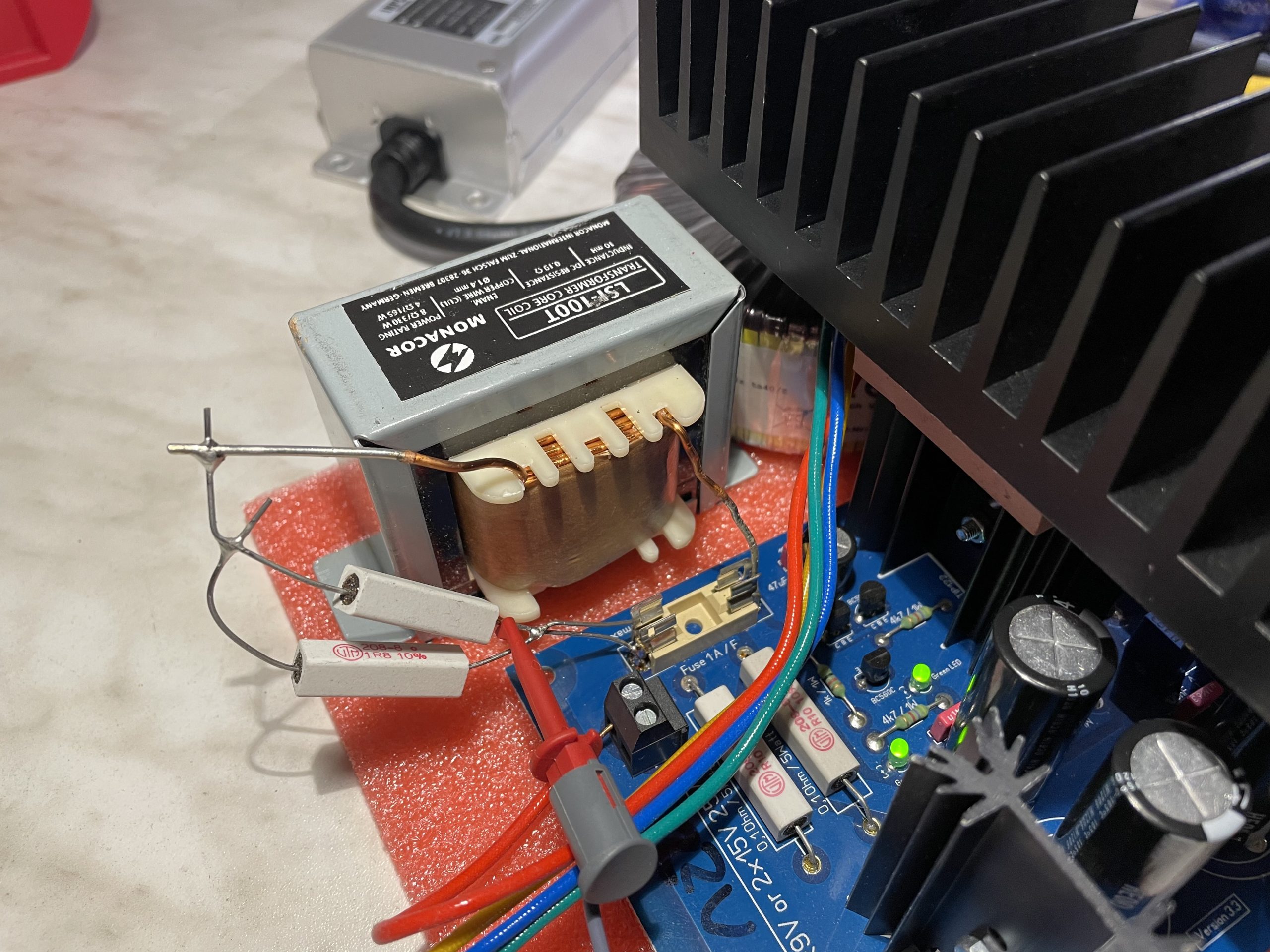
A picture detail of how to easily do this tweak. I just soldered the combination of the Rseries (1 Ohm) and a 10mH Monacor coil at the position of the fuse. With this there is less danger of large damage at short period overload, So I left it out
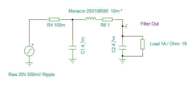
Why 1Ohm and 10mH? Let’s have a look on the impact of adding a choke into the filtering of the RAW DC voltage
I am using TINA Spice simulation for experiments like this
For me the most important feature are the nested simulations, so you can “try out” the impact of a range of component values. At the right you see we need to dampen the resonance. I used a 1 Ohm wire wound resistor to minimize power dissipation and still have a relatively flat curve
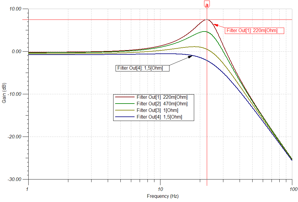
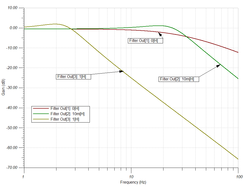
Now I changed the value of the Coil / Choke inductance, still using the 1 Ohm series resistor. As you can see the 10mH Choke adds like -13dB rejection at 100Hz. With 1H it is even MUCH better. But a version with max 0,5 Ohm or so will be hard to find and/or expensive
In terms of sound quality…
me and also several others confirmed that using larger transformers and adding chokes is improving overall sound quality. Feel free to experiment and see for your self what it does for you. After all it is a “DIY HOBBY”, right ?
Conclusions
- PSRR is pretty good! 500kHz -71dB
- In case you need a higher output voltage make sure the RAW DC voltage after the RCRC filter is > Output-Voltage + 5,5 Volt (use 6 Volt to be “safe”)
- If you go beyond raw DC of 25V you need to change the capacitors (they are 25 V versions)
- You can easily increase the output power of the DDDAC PSU by using bigger transformers and bigger heatsinks (you could even parallel TIP122’s – to do like 5A – but I did not cover doubling in this post)
- It is advised to increase the first Capacitor to 10.000uF or 22.000uF when going to BIG loads – but NOT needed (!)
- Adding a choke increases the PSRR with -10 to -15dB depending on load
- Increasing the choke inductance value would help “more” – but be aware of the fact the increased resistance need to be taken into account !! (voltage drop AND power dissipation) Also it gets bulky and expensive 😉 Up to the DIY…
- Added later: Adding a choke and extra resistance will ad extra voltage drop – so “Choke” and “2A” were not combined in this Post (!) You might require a larger transformer or a choke+R with lower series resistance…
- I hope you enjoyed reading this !
If I was unclear or forgot to explain something, please use the feedback function below…
If you want to get an short email notice when my blog is updated, enter it at the right bar (top/mid somewhere…)
30 thoughts on “DDDAC Power Supply (background and tweaks)”
How is it necessary to connect two TIP122 in parallel? any add resistors?
yes, you have to add resistors to both the emitter to compensate for small variances in the Vbe of the TIP122.
I send you email about power supply with two TIP22. Thank you Doede.
Is it possible to create a 5v /2A supply?
I don’t find a transformer 2x9V 120VA?
Thanks!
Sure, if you follow the above guidelines this is possible. I don’t understand why you cannot find 2x9V 120VA? When googled I can find several. For example, Amplimo… https://www.amplimo.nl/images/downloads/ds%20standardrange/48011.pdf
Hi, thank you for the DDDAC power supply circuit and description.
Would it be possible to use a xformer with unequal windings for your PSU circuit? It’s for a 5V supply. I happen to have a 30VA toroidal with 12V and 9V windings. It would save me having to get another xformer.
Regards
Chris
Yes this is absolutely possible !
Thank you, that’s great news. Can I just connect the two windings as shown in your circuit, or do I need to use a zener diode to drop the 12V down to 9V first.
Sorry, i misinterpreted the question, thought you wanted to feed two power supplies from one transformer….
Feeding one power supply with different voltages at at positive and negative cycle is not a good idea, as all power will come from the 12 volt winding. During the phase of the 9 volt nothing will happen. You really need a 100% symmetric winding with center tap.
Greetings doede
Oh, ok. I’ll get the correct transformer then. Many thanks.
Hi Doede,
I want to use a tweaked DDDAC Power Supply for the DD MC Pre Pre. The Pre requires 15 Vdc, whilst the PS in its standard configuration supplies 12Vdc. Since the Pre will draw a current of 100 mA (200 if ever doubled), this is below the max specified value of 1A, hence there is no need to increase the transformer 25VA rating, if I’m correct.
Following the text, I see that I should have the desired 15 Vdc + 6 Vdc margin equaling to 21 Vdc at the end of the rectified and filtered 2nd RC stage (marked above as U1 in red).
But I can’t follow how to decide which Vac secondary I should select. I see in your pictures that your transformer secondary is 18 Vac, which sounds reasonable to me – but also you use a higher rating, 65VA if I read right, since you also indicate having headroom will help in keeping raw Vdc more constant.
In short, I’m lost. I do not know which transformer I should be using. Can you please help? Thanks in advance,
Juan
Hi Juan,
Normally small transformers are having a significant higher Vac output when loaded to their max specifications. Easily 10-20 % more.
You could turn this into your advantage maybe. The original 15 vac transformer most likely will give you already the desired 21-22 V DC to arrive at 15 volt DC.
So just try and load the PSU with 100mA and adjust the output to 15 Volt. It is not critical, 14.5 volt will also work.
Now measure after C2 if you have at least y volt more DC
Otherwise just take a 18vac transformer
Great! Good to go, then.
Thanks,
Hi Doede,
I would try the choke tweaks for my DDDAC1794PCT with 2 decks + Ian Canada FiFoPi Q3 + Crysteck clocks 22/25 , everything powered by a single Doede PSU 12 o 13 Volts + 3.3V regulator (for the clean FiFoPi side), so under 300mA totally.
On the net I found this chokes
1) Hammond 159ZC, 60mH – 2A – 0,7 ohm – 500V
2) Hammond 159ZE, 28mH – 3A – 0,43 ohm – 500V
The latter seems close to your suggestion and keep the added series resistance around 1.4 ohm,
the former has bigger inductance so it should be better for ripple and I think 1.7 ohm vs 1.4 ohm are negligible in my case,
do you agree ? or other considerations let prefere the 28mH ?
Thanks in advance for your help,
Max
Hi Max,
I know from real world experience (Feedback DDDAC users) that the Hammond 159Zc delivered excellent results. So go for that one.
I did not try that one in particular myself, but plan this for the near future. I expect to have very different Chokes in December and will post about my listening experiences.
Thank you very much !
Hi Doede,
sorry to comeback again, I’m not a skilled hobbyst yet, I’m trying…
I got inspired by your “Choke tweak” simulations so I installed Qucs Studio on my PC and started experimenting.
I successfully reproduced your graphs/ripple numbers with L1=10mH / R6=1 ohm . Good.
I put L1=60mH / R6=1 ohm reaching about -47dB ripple at 100Hz. Very good.
Now by increasing C3 (the 2nd one following the coil) to 12.000 / 20.000 microF the ripple goes further down to -54dB / -60dB respectively and it would seem better to me, but…
Do such higher C3 values produce countereffects to the next regulator circuit and/or is it worthwile the C3 increase ?
Thanks again,
Max
Hi Max,
no problem. In fact, it is a good idea to do. It will reduce ripple further and it also will dampen the slight swing up from the Choke in combination with C3.
If it easy to implement for you just go for the 20.000 uF.
Very interesting, actually I was not expecting a positive answer on the subject. Thank you.
Problem now is to find a proper component to fit on the PCB… not so easy.
Unfortunately excellent Nichicon HE series do not provide more than 5600uF for 25V…
I found 22000uF/25V in the snap in Nichicon LGY series, almost similar to HE.
with 30x45mm size and 10mm pin spacing seems it can be accomodated on the PCB
and most of all it is currently available as Mouser part n. 647-LGY1E223MELB45.
Do you think it is okay in C3 position ?
Looks Good to me Max, just give it a shot
Hi Doede,
finally I removed the fuse, mounted the Hammond 159ZC choke + 1ohm resistor and changed the second 4700uF capacitor to 22000uF on the original DoedePSU, so keeping the blu 25VA Talema for now.
(Here no photo upload possible, right ?)
Well, very well I would say !! I confirm what you and others said about overall musical improvements.
My acoustical impressions:
– wider and deeper scene
– better focused instruments
– improved dynamic and transient handling (drums now more realistic)
– improved overall presence effect (with my system especially female voices, choirs, acoustic bass and sax)
As next step I would change to a Toroidy 50VA trafo I have already, do you think it is worthwile for 2 decks + Ian FIFO Pi Q3 ?
I ask because your suggestion is for 100/150VA upgrade…
Thanks a lot !!
Max
Hi Max,
indeed, no pictures …
thanks for the Testimony!! very helpful for the community!
there is no “one and only truth” in terms of the transformer. I know of people swearing a 500VA is the one and only best, LOL
The bigger ones are just so little in extra cost, that bigger is just the easiest choice to “be at the safe side” or so 😉
Goodday Doede,
I am planning to add a bigger transformer to the 5 volt supply, a amplimo 2x 9v toroid 80VA
My question is, can I cut a piece of the board as shown in the picture above and soldering the terminals from the blue transformer in through the holes of 9v connection, the ones used by the blue transformer for connecting the 2x9volt from the amplimo.
Greetings,
Martin.
Hi Martin, sure no problem at all. Make sure to connect the two windings correctly together to create the “center tap”. Use hot – (cold+hot) – cold as the three connections. AC – “center tap” – AC
Good luck and may be post a few words later on on your experience ?
Shure, I’ll come back for how things work out for me, First thing I have to do is rearrange my dac in to two cabinets a dac and a power enclosure 🙂 thank you for the back up
my first impression with same recipe as max uses gives almost a same sort of sound change too.
It runs for three days now and can say that it was worth every penny.
Only the 12 Volt side is done now, the 12 Volt I use for the mainboard and “clean”side of the fifopi Q7 with Acclusion 45/49 clocks via a New class D regulator. The 5 volt is for the “dirty” side of the fifopi only, don’t know if you can win here some extra’s, maybe in the future.
The authority of the acoustic bass is the first what strikes me, less blur in the lower register. With that it seems that there is more room for details and space in 3D , so also more surrounding space of each instrument and when turn up the volume there is more punch.
Fresh in my mind was a concert of Kayhan Kalhor on kemençe ,Tristan Driessens ud ,Pouyan Ataie santur ,Tony Overwater violone/bass and Vinsent Planjer on percussie, The longest night, a concert in Amare -The Hague.
The kemençe is a spike fiddle with some times a harsh sound when bowed what goes right to the soul when Kayhan play that way and that happen again yesterday, goosebumps and wet eyes listening to Silent City, a elegy for Halabjah, a Koerdisch city razed by Saddam Hussein.
By then I know, if the sound is so close to reality, I’m done, finito, (for now hahaha)
Martin.
Hi Martin,
thanks for the detailed report. It is 1:1 with my experience when I did my tests with the chokes. I will post soon on this!
Doede