The DD Moving Coil PRE PRE Amplifier

Doede’s (DDDAC) “DD MC PRE PRE”
“Something completely different”
I too listen a lot to vinyl (LPs). Mainly inspired by Marco and Dick, who are playing with their restored Garrard series and brought their beautiful arm “Groove Master” to the market, I decided to beef up my analog playing gear. First, I built a sort of Linn LP12 clone. The arm / cartridge combination is an Ekos SE with matching LINN Kandid cartridge. An excellent combination I must say… Sounds extremely detailed and sweet. There is a photo book impression on this blog on what I did. I use this turntable mostly for sweet (female vocals) high-end music and jazz/classical recordings.

In the LINN DD DEK, other than the original AC motor, I use a Swiss DC motor and developed my own (what else did you expect?) optical speed control device. The unit below is a self-coded Arduino based setup with PID control and 12-bit industrial DAC to generate the DC Voltage for the DC-Motor. Optical feedback from the platter is fed back to the unit to keep rotations at exactly the desired speed. It has all kind of helpful settings and information on the display. If you are interested what I did here, just send me a private mail. Happy to share…

The second adventure was building a Garrard 301 with the Audio Creative Groove Master-II and a “Silber Meister SPU” from Ortofon. As there was space for a second arm, I mounted my “old” Ekos 1 arm with a Linn Krystal cartridge. Not sure if I need this, but hey, why put in the drawer? The Garrard 301 with this arm and cartridge plays very dynamic, tight bass, lots of pressure. I use this for older recordings and pop music.

Here too, I developed my own Arduino-controlled “pure power sine generator” to control the 220V AC motor… It also contains features like AC-Voltage output setting, AC frequency, speed control, saving settings in EEPROM and much more. If you are interested send me a private mail. Happy to share…

With both turntable setups, it is possible to create a beautiful analog piece of music. Until a few years ago, I used to play with a set of Sowter MC step up transformers with excellent results. Still, I kept thinking if it could be even “better”; the bass remained a bit soft (compared to digital) and I had the feeling there was room for improvement, especially in terms of spatial image and ultrafine dynamics.
My thinking was to develop an active MC PRE PRE to solve this “problem”. Only a PRE PRE because I already had the Phonodude, and there was need to change that beauty! As usual, I didn’t want anything standard out of the box, like an uncreative low noise opamp circuit or similar. I wanted something totally out of the box addressing the needs and difficulties of the concept of a MC PRE PRE and make it as close as I could to a Tube amplifier to match the Phonodude Tube RIAA amplifier. For the simple reason I am till today convinced that the inherent linearity of tubes is the main reason they sound so great. If you do not like tubes and rather prefer opamps – stop reading here – There is nothing to see going on 😉
A few considerations for the new MC PRE PRE:
- There should be no coupling capacitor at the input because of the extremely fine input signals and the noise contribution the impedance of the capacitor will induce at that spot.
- Noise contribution had to be very low. Typical goal >70dB S/N ratio @ 0,5mV input signal.
- No opamps or anything needing NFB….
- A nice linear tube without negative feedback would be optimal, but they generate too much noise for these low signal levels.
- A J-FET at the input, mmmmhhh, yes, that’s not really new, but it works very much like a tube. Unfortunately, most designs have the problem of keeping the power supply interfering signals (noise and hum) at bay (PSRR has to be extremely high and that doesn’t really work well with the standard J-FET circuits you will find on the WEB). Also, the Power Supply Line is always in the signal path and normally only decoupled with a Elco capacitor (which again is in the signal path…)
I have been in pain for a long time and, as always, the ideas come naturally at a certain point…
After many light bulbs going “on” and “off”, finally one stayed “on”
A circuit idea and design goals were defined and I was ready to start developing:
- To amplify the incoming signal, use a voltage controlled current source (VCCS), so that with a single resistor as load, you can do a linear I/V conversion directly to the common ground so Output Signal will be not seeing the PSU directly. (Just like in the DDDAC1794 I/V conversion…). The MC input is the voltage, controlling a current source (a J-FET), which will generate the output voltage by just running the current through a passive resistor. PSSR, DC-Bias and output voltage swing will be an issue, so we need more:
- Take another CONSTANT current source (CCS) that provides more current than the first one and let it drive the earlier mentioned stage. Some current will be “left over”. This differential “rest” current will flow to the output in a (Rload) load resistor. This means that the I/V stage works neatly in class A so there is DC-Bias at the output to allow for a voltage swing of the output signal around the DC-Point. A coupling capacitor is needed when your RIAA amplifier has none (Like the Phonodude). As a result, you kind of modulate the current through the resistor with the lower varying current. Result is amplified signal!
- The CCS must be as high impedance as possible, to have high PSRR. J-FETs do not do this, so it need to be a cascaded J-FET setup. This creates a CCS with very high output impedance in the Mohm range.
- Close off the design by feeding it with a very low-noise embedded Tent Shunt.
The simplified circuit looks like this:
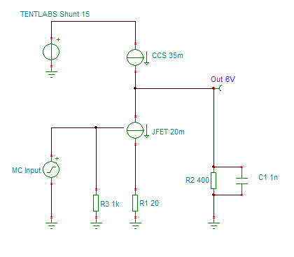
Probably impossible to imagine, so here is the basic simplified circuit. The MC input signal controls the first bottom JFET, which is basically a VCCS.
The cascaded J-FET (CCS) above will now kind of supply extra current, which does not flow through the JFET into R2 and generates the DC-Bias. Gain is provided by selecting the right value of R2 and C1 is just a HF noise filter.
Let’s look in more detail how this works…
By choosing the values of the resistors and current, you can obtain a gain of 5 to 25 times – This can be made adjustable by taking trimmers instead of fix value resistors. Actually, due to the spread of J-FETs you have to make it adjustable…. More to this later on…
At the right is the full circuit. click for larger version.

- Thanks to the top current source, the influence of the supply voltage noise and ripple remains very small. The output impedance is >1Mohm. Versus the output resistance of a few hundred ohms this results in a SRPP of >70dB. Already in addition to the already high SRPP and low noise of the Tent Shunt. In fact, by this topology, you keep away influence from the power supply as far as possible.
- There is (virtually) no power supply in the signal path like in classic “J-FET common source” topologies.
- Noise needs to be addressed, so I choose to connect 10x BF861B in parallel to reduce the noise (Square n better -> 10dB less noise compared to one single FET). These J-FETs are having a great combination of noise contribution and transconductance. Paralleling also provides more bias current and hence a 10x lower output resistance of the amplifier output. The current source has 20 JFETs in parallel as cascade to increase the output impedance seen by the output stage.

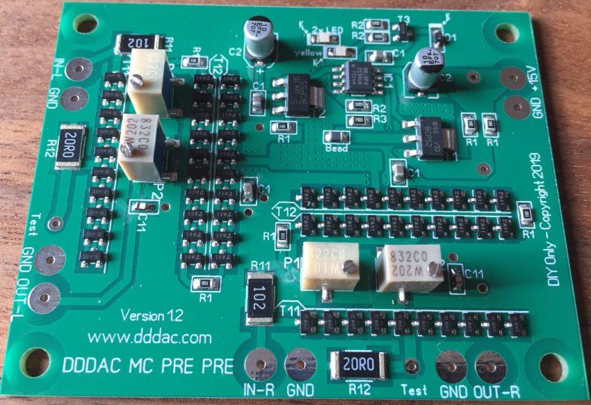
The PRE PRE is constructed as a small stereo PCB with only SMD parts (almost 100 pieces) to keep the signal paths short and for ease of implementation. So, it is ready to go – no further components to be soldered on the PCB. The nice extra is, that because of the current output, you can simply connect the boards in parallel!! Yes, you can already hear it coming… just like in the DDDAC1794… each doubling of the boards provides 3dB of improved S/N ratio.
The DD MC PRE PRE only needs a few external components and is easy to connect. Depending on the next stage (typically RIAA amplifier) you need a couple capacitor of your choice…. Gain adjustment is “factory set”. This is probably the easiest to implement design I ever made!


In my personal setup I decided to use two boards in 2x mono mode. Of course, I measured the signal to noise distance (SNR) with my AP gear and I came up with (A-weighted) ~80dB against 1.2mV @ 22-22kHz – (My Kandid cartridge outputs 1.23mV at 1kHz 10cm/sec). Compared to the design goal of 70dB @ 0,5mV that would be indeed better than 72dB with an input of 500uV.
Some more background Information:
I had a small batch of PCBs populated with the SMD parts (one is just not worth it). They look bigger in the picture, but they are only like 6×7.5 cm in reallife. Like the DDDAC1794, they can (yes…) be stacked to work in parallel. Each board draws about 90-100mA, so it’s no problem to feed them with a nice power supply without outraging dimensions.

On the stacking benefit the following… (You know me with my modular stacking habit 😉
This board is a stereo board, but it can be used in Mono-Mode as well. Just connect the L&R inputs together and also tie together the L&R outputs. No problem, as it is all current sourcing.
By doing so, you will improve the S/N ratio by another 3dB and will improve the sound stage, thanks to double mono setup… Not sure if more stacked boards are improving the real-world experience even more, but technically there is no real limit.
OK, so far, all works fine, no hum issues etc. It runs on any 15 Volt DC power supply. I am using a stock DDDAC Power Supply trimmed at 15V DC for example (see image above).
Just for test-fun, I also tried a simple PSU setup, consisting of ONLY a bridge rectifier and a 100uF electrolyte capacitor (yes, only 100uF…). This resulted in a very rough 15V DC supply with an AC 100Hz ripple of 3V pk-pk(!!). I did that on purpose, to check the working of the double current source topology. On full volume (not playing music and probably speaker damaging level when the needle would drop on the LP) you could hear some 100Hz underneath the noise. This shows the excellent work of the blocking effect of the top CCS. LOL, try this with a standard JFET Common Source Circuit… The whole board draws as little as 90-100mA in total, so when used in double Mono-Mode, the power consumption is moderate and hence no need for “BIG” power supplies.
How does it measure?
Compared to common step-up transformers the bandwidth of the DD MC PRE PRE is pretty good. It starts at DC and the -3dB point is above the 200kHz mark of my AP test setup. The 200kHz mark is -1,5dB and only 0,5dB at 100kHz. Note, the low frequency cut-off will depend on the OUTPUT coupling capacitor you will use. On my DDDAC Website I have a nice table for this: LINK TO DDDAC SITE


At the left you will see the FFT measurement showing low distortion and low hum components (A-weighted). This is at a, compared to typical MC cartridges, high signal level of 10mV input (!). The d2 distortion is the only dominant one at roughly -60dB which equals 0,1% THD only. In practice the amplifier is distortion and hum “free”.
Final specifications:
| Gain | 5 to 25 (will be factory set on demand) |
| Input Impedance | 1k Ohm *) |
| Output Impedance | Aprox. 200 – 500 Ohm |
| Bandwidth (within 0 – 1,5dB) | 0 – 200kHz |
| Distortion at 10mV signal input | d2: 0,1% d3: 0,0025% |
| Output noise with inputs shorted (i.e. amplifier noise contribution) | ~20nV / SQRT(Hz) |
| Size | 58 x 73 mm (Mounting holes 50 x 65 mm – Dia. 3,5 mm) |
| Power supply (DC) | ~15V DC >100mA (per board) Audio Grade recommended. Minimum 13.0V for proper functioning of embedded Tent Shunt Regulator |

Everything just Perfect?
Well, there is no benefit without a disadvantage of course…
Here too, I couldn’t get around the law of conservation of problems, LOL.
• The J-FETs have a considerable spread of their V/I curve (the voltage-to-current source ratio), so you never know in advance what the exact specification of the transconductance (S or gm) for the delivered batch will be.
• The only way to overcome this, is to adjust the current for each board. And by doing so, setting the GAIN as well, which comes in handy by the way (so another advantage…) In fact, not easy to accomplish as you have two potentiometers / trimmers which influence each other settings. I found it only works well if it is done on the test bench with the AP setup. Now you can adjust the gain within a few tenth of a dB. Once set, it doesn’t drift anymore, it’s rock solid. So basically, it will become a “factory set adjustment”.
• As mentioned, the gain can be set perfectly as desired to any value between 5 and 25. Channel unbalance can be avoided this way. By the way, a gain of 10x or 20x is pretty standard, but any value between 5 and 25 is possible.
Conclusions
- The measurements show that this is all VERY good for a discrete design. The DD PRE PRE has no need at all to hang around in the shadow from any other MC amplifier! On the contrary. It is difficult to get any better as the noise is almost at the level of the thermal noise of the cartridge’s coil DC resistance itself. Of course, you can’t get any better than thermal noise… Physical laws and all that.
- Sound wise, the DD MC PRE PRE amplifier benefits greatly from the lack of any negative feedback. It is just very linear, sounds open and natural as any well-designed tube amplifier, only d2 and almost no d3. You can easily hear that well; it sounds beautifully natural and never sharp or muddled. Compared to the Sowter transformers (I can still select the one or the other in my setup) it is so much tighter in bass and delivers a great spatial sound with low level detail. I am more than happy with this development. Even if it is mine to say…
- I’ve been playing music with this design for over a few years now to my complete satisfaction. The pre-pre sounds beautifully spacious, very finely detailed and with a tight bass. The self-noise is clearly below the vinyl noise itself.
- I call “Mission Completed” to develop something “completely different” and fantastic sounding.
- One last consideration; it is highly recommended to use a high-end coupling capacitor at the output to block the DC-Bias. It is worth it to get the maximum out of the amplifier. I use for example Mundorf Gold Silver Oil. But there are many other good brands of course. Your personal choice!
Interested? Want to try it for yourself (at no risk)?
As mentioned, I had several boards made. I do not need them all obviously. I will offer these boards at a reasonable price of 250 Euro (plus shipping cost). You will have no risk. If you are not satisfied and convinced it is worth staying in your setup you can return it within 45 days after receipt, I will 100% refund the cost of the board. No problem at all. Afterall it is just a hobby, right?
Just PM me or use the contactform. CONTACT FORM

30-day satisfaction guarantee…
One thought on “The DD Moving Coil PRE PRE Amplifier”
Hello from Bonn in Germany,
First of all, Many thanks Doede for the formidable effort in designing / publishing this!
One question with your permission:
Which input capacitance does the module exhibit?
Thanks,
Best regards,
Adrian