My UltraCap experiments
Introduction
Inspired by the many reports on the audiophile improvements when using UltraCaps (or super capacitors) in Audio applications, I decided it was time to start looking into this subject myself. For starters I wanted do some tests with it on my own DDDAC. Of course I am also interested in the technical aspects and possible use for future projects. But as always, get some facts first and listen to some music ….
There are many, many articles on the WEB going into depth on the Ultra capacitor technology itself. I will not do that. I will consider it to be a basic component and do my experiments…
OK, Elephant in the room? There are “plug & play” solutions out there. For example from Ian Canada, some real nice P&P boards, which does all charging and controlling and as it seems, relatively idiot proof. So why is there a need for me to go into this? Well, I just want to post something much more generic and give ideas to the DIY community on other ways of doing stuff. More generic means it will serve a wider range of applications and wider audience.
Time to get into the workshop and check this out…..

First (technical) thoughts
My “research” and own thoughts led to a view, that there are basically three ways:
First:
Use one Power supply and have the ultra Cap (module) connected in parallel as a kind of voltage follower (make sure the PSU can start at zero Volt and limit its current). Also it should be able to handle power loss heat dissipation.
Pro: Easy solution and no worries on max voltage or charging specifics
Con: With typical power supplies (like 1A or 2A) charging can take a lonnnnggggg time before you are on the desired supply voltage (assume 100F: with 1A and 12V supply for example, it will take t = (dV*C) / I = (12V*100F) / 1A = 1200 sec = 20 Minutes (!!) – So before enjoying music after switching on, you can do the dishes or mow your lawn 😉
Second:
Have one PSU and electronic circuit controlling it like this: The PSU is connected to the appliance (so it starts working immediately) and with extra current available from the PSU (control circuit needed), start to charge the UltraCap till it is full. The controller checks the voltages (like is the UC full?) and when it is “full” switches the UltraCap in parallel to the PSU and supports the supply output with its specific features.
Pro: The appliance will work immediately at power on
Con: Need for special control circuitry. Again with large UC it can take a long time before it is fully charged and contributes its sound improvements. Also there will be a switch (relay or MOSFET in series between UC and appliance (not sure if that is really bad, but for sure it is not helping sound wise – at best neutral) – I believe this is how Ian’s conditioners work basically; correct me I am wrong please…
Third:
Have two PSU and electronic circuit controlling it like this: The UltraCap is connected without any switch or MOSFET to the appliance. A BIG FAT PSU with Constant Current possibility of say 10A or 20A will fast charge the UC Bank. As soon as the voltage is close to the “Audio” PSU, the audio PSU will be switched in parallel to the UC (and hence connects directly to the appliance). BIG PSU is disconnected and now the Audio PSU takes over while being connected to the appliance together with the parallel UC, so it can do its audio magic.
Pro: The appliance will start working after only 20-45 seconds (Time to boot your PI streamer for example. The UC is connected directly to the appliance close to the point of entry. (For what that is worth, but sounds like a common good idea to me)
Con: Need for special control circuitry. And of course an extra power supply. The good news is, this does need to be an expensive “high end thing” Any heavy duty LED driver or Acid-Lead Battery charger will do the job and will cost less than one high end Cinch Connector 😉
For obvious reasons I decided to go for the third option !
What UltraCaps to use?
Excellent point. As always there are many choices and it seems there are some favorites. But some are crazy expensive and I am not even sure what are the best specs to look at? Leakage, Value (F) or ESR? One thing, the bigger they get, the lower the ESR… and…. if you want larger banks, it can cut deep into your budget. I wanted to do some experiments only. So looking for cheap solutions should be allowed, right?

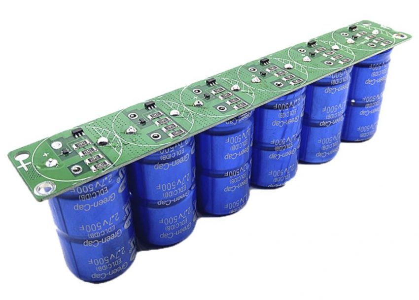
Here is the first “cheap solution”: a 6x 500F Bank for up to 16 Volt. The UC used in here have an ESR of ~3mOhm. not bad and total price for this module was 30 Euro including shipping from China. A man cannot do much wrong with this, price wise it is…

I also had in mind to try out 3,3 and 5 Volt supplies, so also ordered a few similar modules with two 500F UC in series. These cost ~ 15 Euro including shipping from China 😉
want to read the datasheet of the capacitors used in these modules? here it is: http://blog.dddac.com/wp-content/uploads/Green-Cap-DATA-SHEET-DB-2-7V-500F-W-35065-_191030.pdf
Considerations on how to set up the experiment
OK, UltraCaps are a known factor now and the third option with two power supplies is the route to go. Two things left: Control circuitry and the second power supply. As I wanted to stay flexible I, decided to (again) use an Arduino controller as heart of the control unit. For total arbitrary reasons I picked the Nano this time. This is like a miniature Uno and has everything onboard for this simple task. For the second power supply I went into eBay and found a LED driver with 10A constant current function. In hindsight not a super good choice as it only went to 12 Volt. Meaning, when you want to run the DDDAC with 12,5 Volt or use the Magic Power supply (13,5V) you would come not really close… it would be good if you could charge a bit higher. I also ordered an lead/acid battery charger which will be able to get to 13,8 Volt – But it does not matter, the principle stays the same !!
Design of UltraCap Power Supply

Here is the complete circuitry I used for the test-setup. The Arduino Nano controls one of the typical “Arduino” Relay boards. Great stuff, Logic Level control, optically isolated and 10A relay contacts. At power up of the whole DAC/system the Arduino code starts doing its work. R3 is activated and the ground of the Charger PSU is connected to the ground of the UC module.
This will start the charging of the UC . The code will check the voltage at the A/D converter inputs A0 and A1. The voltage dividers (3:1) are to protect the Nano and create a max level input level for the analog pins of 15Volt (Nano works with up to 5Volt) After roughly 45 seconds the UC voltage is at the ~ level of the DDDAC PSU. The Nano see this in an IF statement and will start the following action sequence :
- Activate R1 (disconnects mains power of charger PSU)
- Activate R2 (disconnects the charger PSU plus pole and connects the DDDAC PSU to the UC)
- Deactivate R3, so the GND of the charger PSU is also disconnected from audio GND
- Activate R4, so the GND of the Arduino is now isolated from the audio GND
By doing this I will be 100% sure that in the status quo, only the DDAC PSU and UC are active in the audio circuit. All the rest is isolated and/or powered down… Looks like a solid audiophile design rule to me (just to be on the safe side…) The status quo will stay as long as the Nano is powered on. The program resets and start again its one time routine again after switching on and off again.

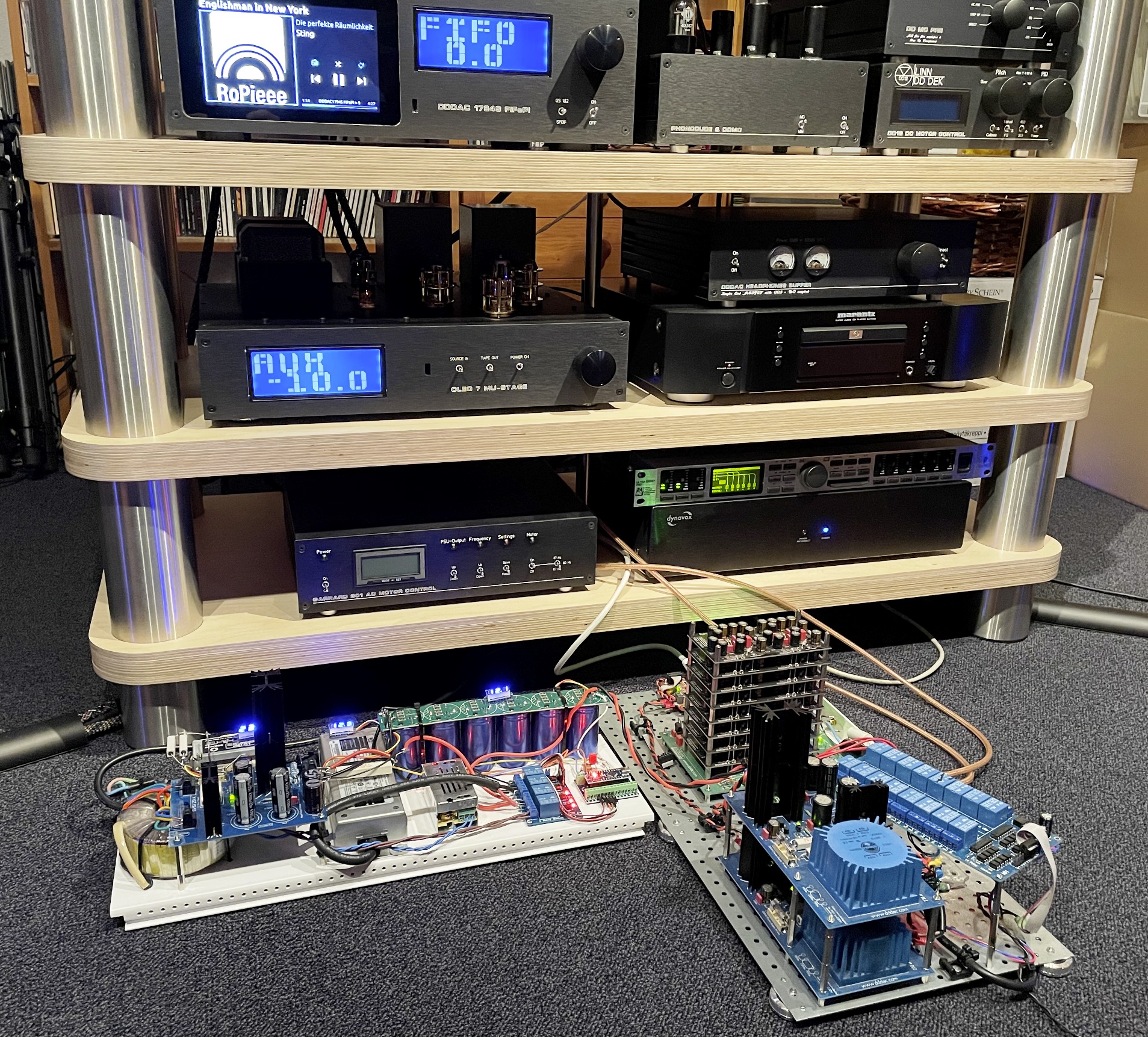
🙂 Now this is how real bench experiments look like. A mess of wires and equipment surrounding it… But at the end it all worked as expected and I could build a somewhat neater, and more solid version (see further below)

Something I had issues with: The output resistor of the DDDAC PSU must be shorted with a piece of wire. If not done, the time constant of R6 and the UC (~ 6 seconds), will cause a long “slowly dying oscillation with a period of 10 seconds or so” of the output voltage before it finally settles…
Warning:
When using other power supplies the only important things is, they will be able to deliver on top of the required current for the DAC some extra current (1A or so?) to charge the last few hundred mVolt after the UC is connected to the PSU. Also, it should have some form of current limiting as the low impedance of the UC can start with currents up to easily 50A even when the delta voltage is like a few hundred mVolt (!) See below plot also.
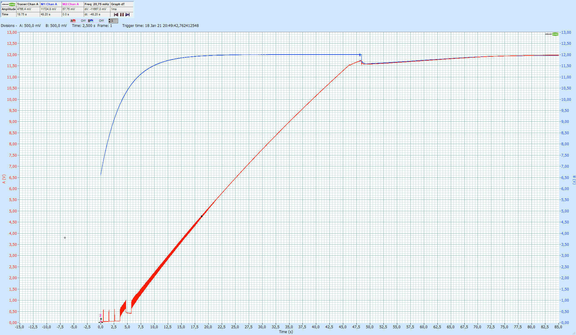
I can use my CleverScope for logging signals at a very low speed and over a long time. Very helpful in situations like this. In the plot the operation is nicely visualized.
The blue curve is the DDDAC PSU – you recognize the soft start. The red curve is the fast (!) charging of the ultra capacitor. In the beginning a few hiccups from the PSU to get the CC started. With the UltraCap at zero volt it is like a hard short cut ! From the linearity of the curve, you can read that the capacitor is charged with constant current. From this curve it is also easy to calculate the total effective capacitance as: C = (I / dV) * dt = (12A / 11,5V) * 45sec ~ 50F (so the 500F are in reality more like 300F…) – BUT at the top of the curve at lower currents the UltraCap shows more capacity. I checked this a few times and came to values like 60-70F. Nevertheless still a lot of Farad at hand!
Below are a few pictures of the experimental setup I made with my DDDAC 8 Deck Test Unit
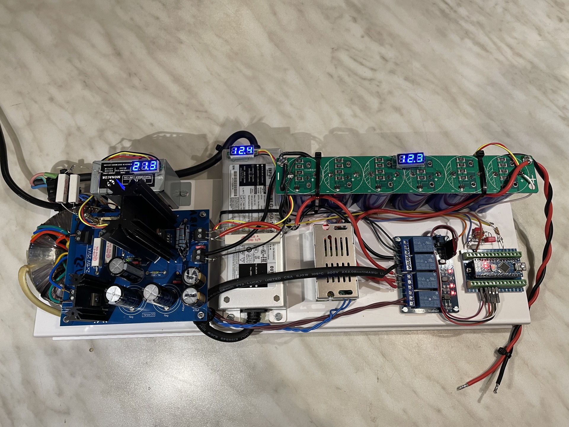
Already looking pretty slick 🙂 Now the wiring is taken care of, things are tided up. I added a few of the (AliExpress cheap) voltage indicators (self powered by the voltage you measure – works > 3 V). A small 5 V PSU supplies the Arduino Nano and the Relay board.
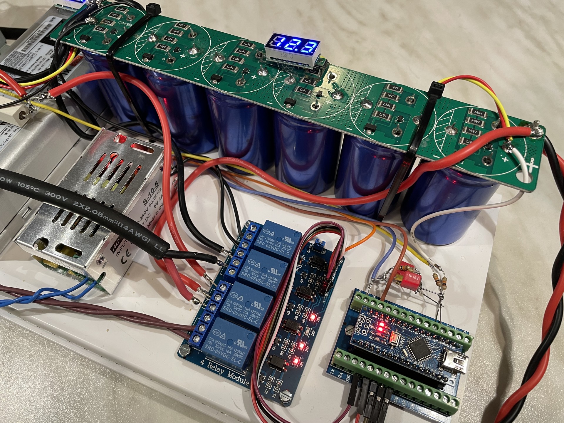
A closer view of the Arduino Nano control section – I decided to use the carrier board. Now it is easy to unplug and re-plug the Nano to update the code back at the PC in my Home Office.

Another view. Easy to recognize at the larger picture (click on it) that the output resistor (0,1 Ohm in the standard kit) is shorted with a piece of wire. The left voltage indicator shows the RAW DC. Good to keep an exe on it. Read my DDDAC power supply post for more background.
Below is my DDDAC 8 Deck Test setup. I used this over the years to do listening tests as it is easy to access and with the relay module I can do TRUE A-B comparisons… It is maybe not the latest and top of the bill, but features 8 of the earlier boards (no Tent) and standard mainboard, but with an Ian Canada FIFOPI – but with standard clocks. The output is with a set of Audio Creative output transformers. The long wire with the switch, is the “remote control” for the listening position 😉 No surprise I can switch this time between the two power supplies….

Listening….

I had everything burn in for a day or so. Started with a known great analog recording from the Dutch high end recording label STS. They make beautiful live recordings and also sell their Master Tapes. I also have the master tape of this album. With the title track I am normally able to make good judgements on what tweaks does to the sound quality…
First time switching between both power supplies immediately did something to my ears. That was my first reaction. But I was not sure what it exactly was. So putting on several more tracks from typical high end stuff to “normal” music 😉
On some tracks I could barely hear any difference, let alone to say if any of both was “better”. On the other hand on tracks where for all there is much room and texture in instruments and voices, it became clear that the UltraCap is creating a clearer contour and image, voices come to the front a bit. Where if you would say the DDDAC PSU is somewhat laid back the UC has more bite in comparison… The UC seems to add dynamics to the whole picture. Also textures get somewhat more recognizable.
BIG differences, playing against the wall? Sorry to disappoint, but no way. I even believe that it also could be dependent of existing audio setup and your listening preference if you would say this is an improvement. But, as always with tweaks, if you like what you hear, you keep it. Even when it was small, you know you came a (little) step forwards in enjoying your music and our beloved audio hobby 🙂
Conclusions
For me personally this was motivating to continue experimenting with UltraCaps as a way to improve sound quality. But still lots of work to be done. What about analog equipment, like my MC pre pre running on 15 volt? and all the 5 volt and 3,3 Volt supplies in the DDDAC? What about the direct heated filaments in my 300B amplifier ? What about new developments? Small super capacitors close to the chips as decoupling? Good I retire end of February !! LOL !
- The experiment shows this is a whole new field to explore. UltraCaps just do something and it is worth to keep going on finding applications for it in the whole audio chain
- NEVER ever just connect an (for sure empty) UltraCap to your current power supply. It will draw whatever current can physically comes out of the PSU. If there is a Constant Current limit, ok that is fine, anything else will trigger a shutdown or will burn out your power supply or best case blow the fuse
- If you have little headroom in your audio PSU (=not so much current “left over for charging purposes”), it will be a drag to charge an UltraCap (Bank) with that…. Can be done. But I think it is impractical
- Oh, not to forget, the impact of the 10mH choke in the DDDAC power supply as such. Of course I did not used a true (high end) power supply choke. So you could say it only can get even better? At least I could notice indeed an slight improvement when the choke was in the circuit versus not. Impact was smaller than the UltraCap to put things in perspective. To be honest, I believe for this purpose the bigger ones will have more impact (Nothing beats cubic inch or something like that…)
Next steps?
As in my conclusions already stated…. YES this is screaming for more experiments and not only with the DDDAC DAC, also my other analog equipment where lower DC voltages are used. MC Pre Pre, Tumos amplifier, filament heaters, headphones amplifier, and so on…
Also with further developments I should really start thinking about implementing local embedded UltraCap solutions. May be not this BIG banks but something with more handy formats…. like this for example.
Another wild thought: Parallel multiple UltraCap modules like I used and just charge them and let them supply the DAC without any further power supply. Assuming you would allow 1 Volt drop to be acceptable, you would need for 10 minutes music 600F (I timed this …) Recharging would take 30 seconds with a 20A current source. Not very practical I admit. I listened for a minute or so to my setup from above with only the UltraCap and indeed it does a very small bit. To be honest I would not do this – did not seem worth the trouble.
Well, whenever it comes, it will definitively show up here – subscribe to my email notification for new posts !! Then you won’t miss anything 🙂
BACKUP: the Arduino Nano CODE
Here is the code I used for this experiment. This is 100% BETA (!!) Stuff, so no support, no updates of course – just for the “makers” among us who like to see what I did or who want to copy the above experiment…. (which is fine for DIY use of course – NOT for commercial use…. I need to keep saying this I am afraid.
OK, I could not upload (for security reasons) the original Arduino Format. So it is a PDF file. A bit crappy to read, but not impossible…. If you would like to have the original Arduino sketch file format, write me a comment below or an email. I will send it to you.
http://blog.dddac.com/wp-content/uploads/DDDAC-Arduino-Code-Ultracap-Power-supply.pdf