Upgrading my CLEO 6 Tube preamplifier to CLEO 7
Introduction
For many years now, I have been using Dick’s (Audio Creative) N30P Mu Stage Design. He called it the Cleo 6. It is a great double mono MU-Stage amplifier (see circuits) with top components. Over the years I started to see the benefit of using Arduino computer boards as a control tool, so I decided to upgrade this preamplifier to the next level of convenient usage: The CLEO 7 🙂
01-10-2020 (component assembly and measurements)
updated circuits PDF v3
01-10-2020 (component assembly and measurements)
updated circuits PDF v3
08-10-2020 (almost ready … new pictures)
11-10-2020 (final)
Here is a gallery of the images only (no text)
http://blog.dddac.com/cleo-7-picture-gallery/
Below are my specification goals:
- Tube Power supply with GE 6X4 and CLCLC filter
- 6N30P (actually 6H30Pi) Mu-Stage with Mundorf Gold-Silver-Oil & V-Cap couple C’s
- Volume and other functions to be Arduino controlled (Both by a rotary encoder at the front panel as well with a IR remote)
- 24 Steps relay driven volume control with individual 2 resistors shunt attenuators
- 6 Source inputs
- 2 Tape Out, independently selected from Source
- 3 outputs: XLR and RCA
- Tube amplifier BIAS points checked by Arduino analog inputs: Power supply voltage, Output voltage and Triode current
- 4×20 LCD display showing all relevant information

At the left you can click to view an updated PDF file with the schematics and other information of the Cleo 7
This is the final version (4)
And here is the link for the Arduino code Click here for code
I designed a PCB which contains the selections, input and outputs, as well the volume control. The Arduino board is embedded on the PCB. This will make my life easy and they (plural; the minimum order was 5 pcs) just arrived. Additional parts and a new chassis were ordered. Next step is to build the control board:

The mainboard control unit
UPDATE 2020-08-19
Next step was to build the control board, write the Arduino code and test everything. Finally all components arrived so I could start building. That has been done now and 95% of the code works fine. As you know software is never ready, so any tweaks will be done later. But the basics are working. The volume control, the selection of the source and tape out as well the Bias Check of the Tube stage.

As you can see in the picture, I am using a generic remote control I found on Ali Express. It has some nice basic buttons which fitted nicely to my desired functions. I have a simple Arduino UNO setup to read the codes and plug these in the code. The display shows the normal condition. It also has a LCD settings menu and Bias check function, but as said, it is all software.
More important, all hardware and the volume control works fine. The number of relays indicate, recognizably, that I choose to go the complex way of shunt volume and not a ladder network. So for 24 steps you need 48 relays 😉 It is quite a puzzle to calculate the resistor values which are actually available, but I managed to have pretty precise 2dB steps and some 4dB steps at the end of the scale.
In the meantime I have dismantled the “old” Cleo 6 and designed the front, back and top plates. I use the software of Schaefer Berlin for this, as for all my projects. This also leads to a nice coherent look of all equipment together you find them here: https://www.schaeffer-ag.de/
Next step is the re-construction of the amplifier and do the functional testing and of course the listening tests!
to be cont’d !!
Hardware assembly and first wiring
UPDATE 2020-09-29
Work in progress!! I will show a few pictures how the assembly is coming along
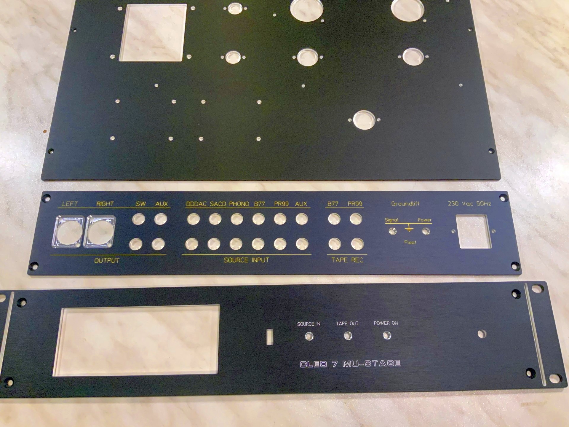
Schaeffer did a good job again – their deliveries got pretty fast (just a week or so) compared to a few years ago. As always perfect quality and first step is to assemble the hardware…
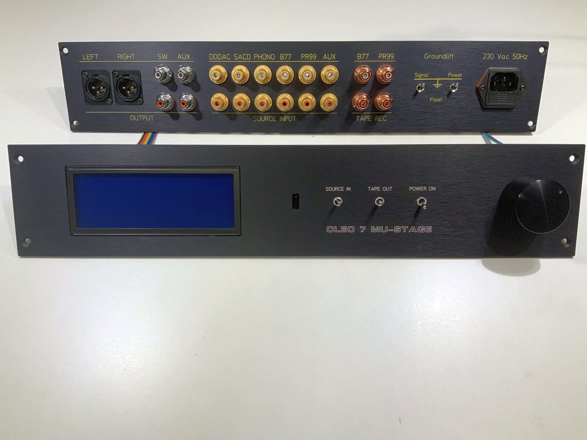
The back and front are assembled. Most parts I buy at Ali express. Takes a while, but so much cheaper and quality is absolutely OK – sometimes I believe that what you buy in European shops is just the same, just 10x more expensive
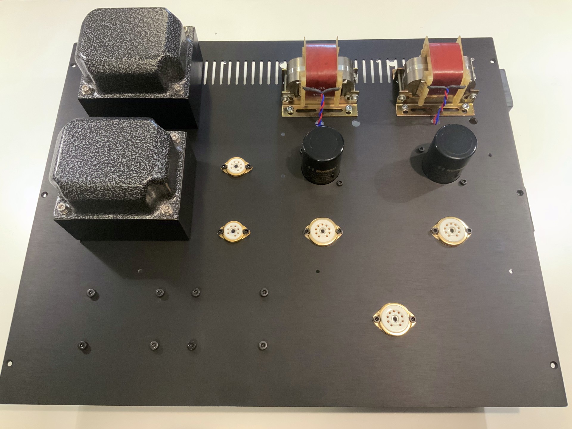
Next step is assembling the top plate. I used the transformers and chokes from the “old” Cleo 6. The WKZ Black gate capacitors I sold on eBay as DIY are paying crazy pricing for them. This easily paid for the whole project 😉 I replaced them with the very nice Mundorf Capacitors (the Electrolyte and Tube Caps)

At the right the view how it looks when the hoods are placed over the Chokes. There are two more chokes but they are under the top plate. Purely optical choice I made following Cleo 6… I also bought new gold plated Tube Sockets.
Only some wiring to be done, LOL – this is a very precise job. It must be correct the first time, so many checks and double checks. Do not forget, later on this is carrying HIGH LETHAL voltages. Very lethal, so you want to be 100% sure when switching on the amplifier, you won’t electrocute yourself or burn your transformer due to shorts in the wiring…
Anyway… my process, to make sure I do everything right, is to follow a simple procedure, starting at 230 Volt AC, follow the power circuit (like heater wires, AC to Tube and DC modules, then the Capacitors and chokes, all the way to the Tubes…. Below is how it will look like at this stage-


UPDATE 2020-09-29
Next step is adding the components. Traditional hard wiring with the help of the wire bridges. The small boards left and right are for the voltage dividers which will supply the TEST voltages to the Arduino (later stage in the story)
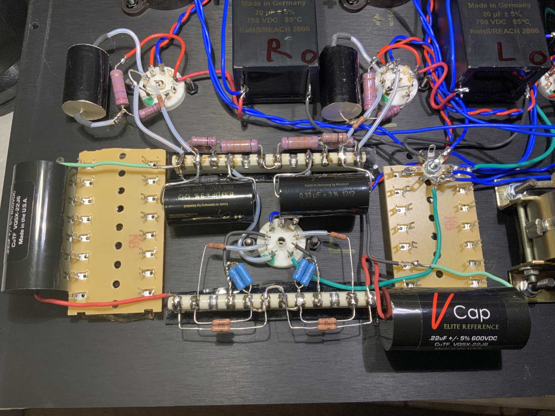
Using Nano Adhesive Tape (Thanks Dick for the tip !!) the capacitors are “glued” to the top plate and soldered. Final wiring is done also. Basically the amplifier is now ready….. so we are ready for……
First Measurements
I have a standard series of analog measurements I do with all my amplifiers. I do it right now, as I wanted to make sure, all is fine before I add the Arduino IO board and assemble the whole chassis. makes sense, right? All measurements are made with Audio Precision System Two 2322… So here we go:
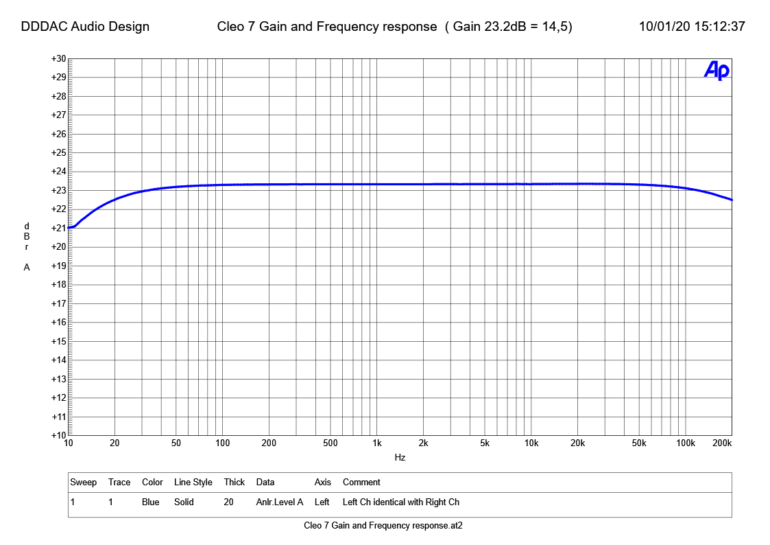
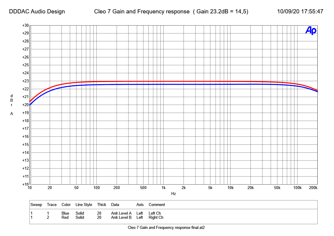
The classic of all – gain and frequency response – Gain is within 1% the same between channels, so I only printed one channel. The bandwidth of a MU-Stage is stunning. The AP “only does up to 200kHz” I think it will go up to 500kHz at the end. A gain of 14,5 means that with a power amp (like mine) with a gain of 0,7 the sensitivity for 50 Watt at 8 Ohm is 1,86 Volt rms; a very practical value.
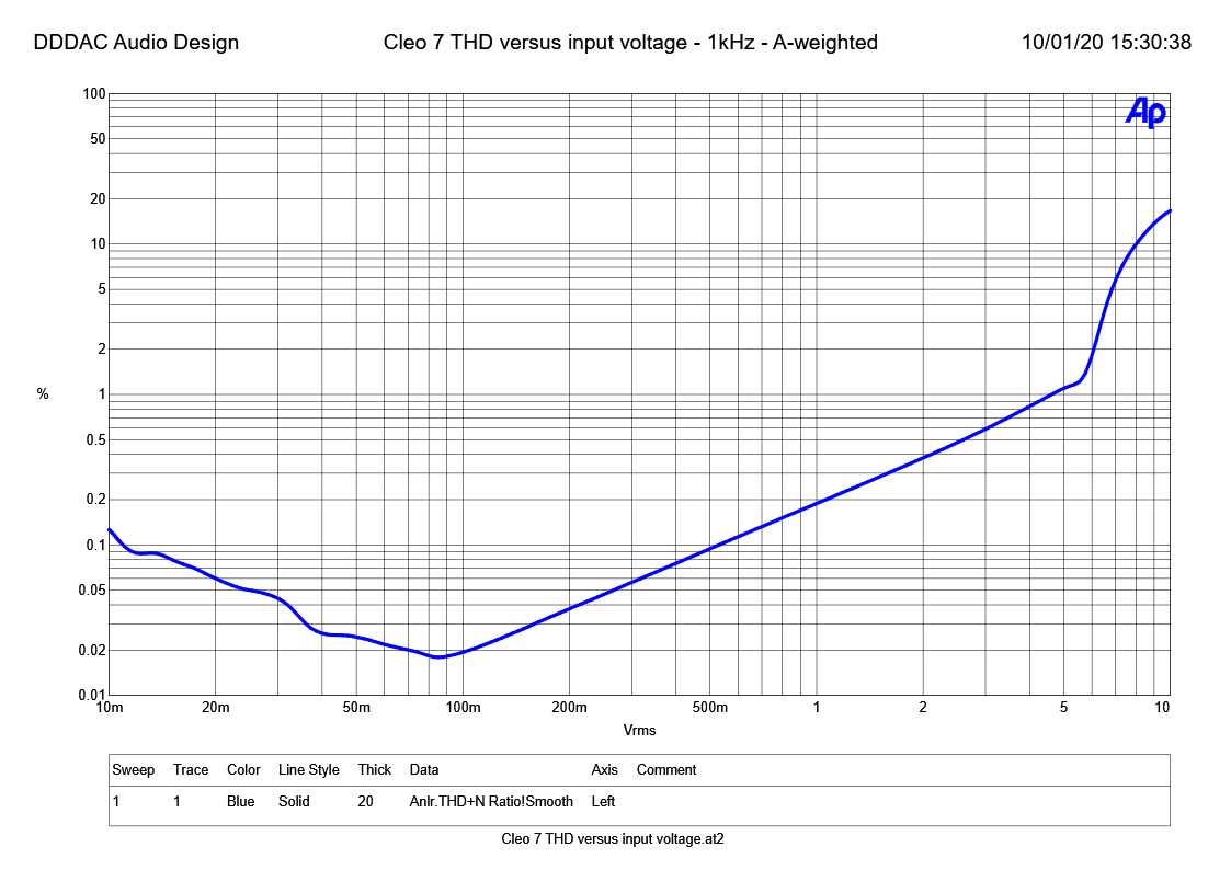
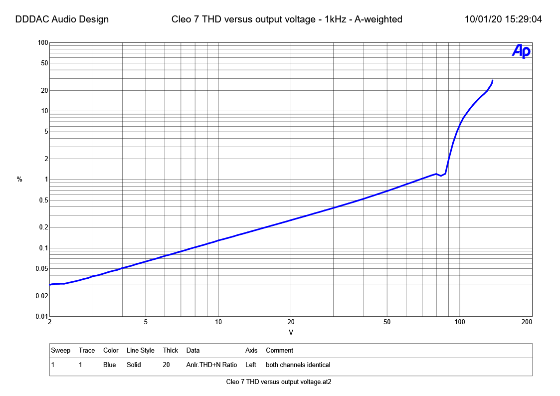
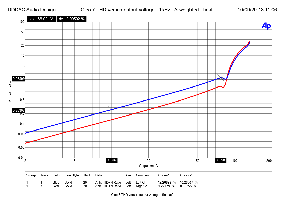
Now two distortion measurements. Above versus the input voltage and below versus the output voltage. Two observations, first, beautiful linear curve (test magazines “say” that is typical for tube amplifiers and wanted behavior for good sound. Secondly, an output of 70Volt rms with 1% THD…. do I need to say more? How much headroom does a man need 😉
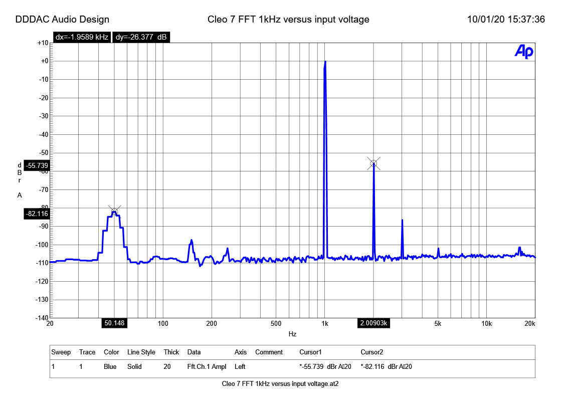
A FFT spectrum analysis always gives a nice holistic view on what is going on in the amplifier. Above is the pure technical measurement. 1 Volt input and no weighting of the distortion curve (typically this would be an A-weighed curve). I see d2 at only -55dB and d3 far below that (=good). The 50Hz hum component remains at a very decent -82dB (remember, the amp is not enclosed yet and just belly up top plate on my bench…)
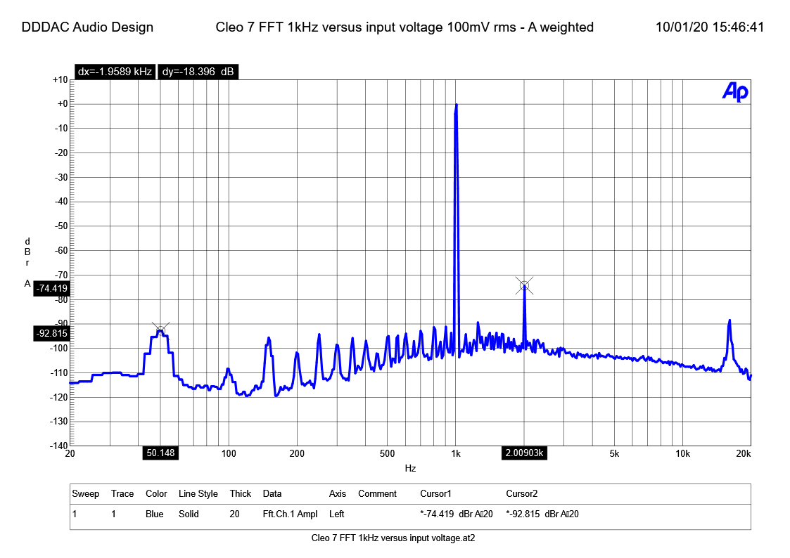
Below is a more realistic picture of your day to day listening situation: 100mV input (-20dB below maximum power output) and corrected for your ears (the A weighed curve). Of course better values now. ONLY a d2 of -74dB and hum at -92dB. d3 is gone….
In summary you could say, the Cleo7 is high bandwidth, with very low distortion and being dead quiet !
UPDATE 2020-10-08
Almost ready
The past days I have been doing lots of wiring and assembly. I added a few things, like the Arduino voltage refence, the bias check parts and a capacitor across the contacts of the relay (for spark reduction). After that I just need to fire the whole thing up, do final testing, debug the Arduino code and finish the code (LOL, Code is NEVER ready). I will also publish the final circuit diagrams and the Arduino Code for those who like to use this or see what I did. And yes, after that, enjoy the music, which was the final goal anyway…
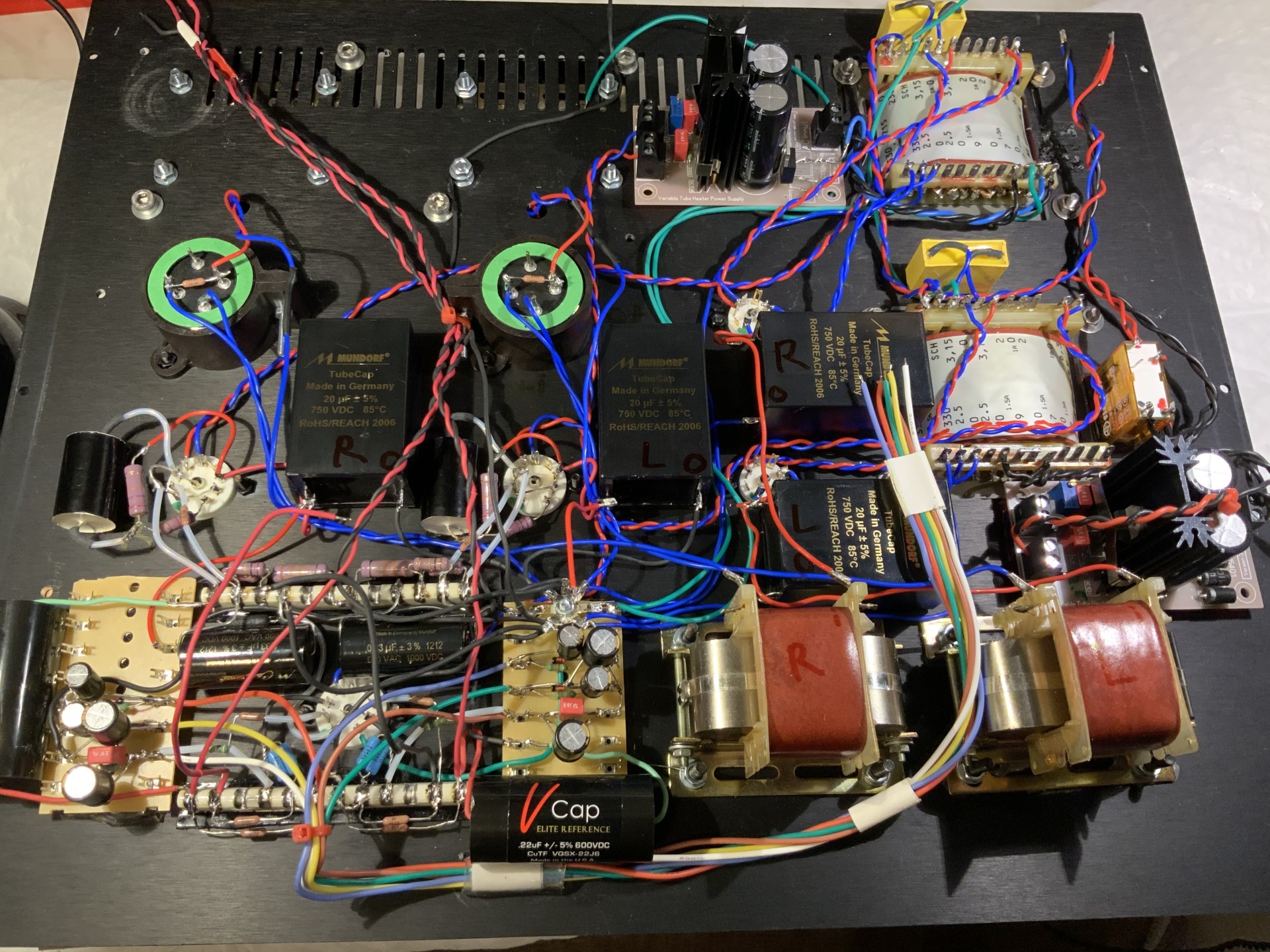
I have now added all final wiring. I stayed strict to the star ground for all ground wiring. At the left bottom you will see two small boards. These carry the parts for the bias voltage check. Reducing the high voltage to low and filtered voltage the Arduino can safely read.
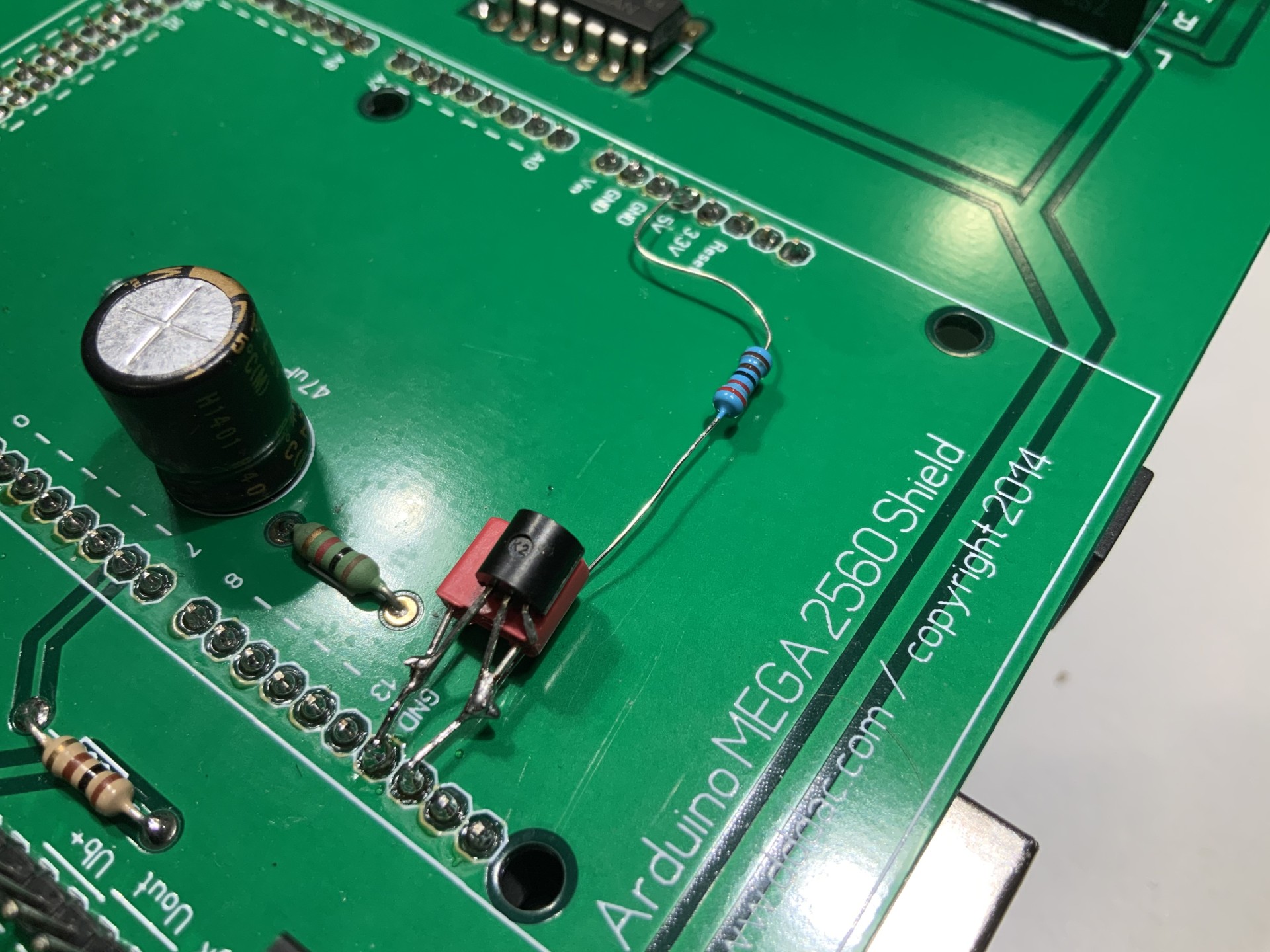
Talking about Arduino reading voltages. The Arduino “normally” uses the “5 Volt” Vb as an A/D conversion reference. This is of course everything but precise. So I decided to add a LM358 2,5 Volt reference. Should have thought about this earlier when designing the PCB LOL 🙂

I pre-wired the back and front plate. This makes it easier to wire the IO Board when the chassis is assembled. By the way, for all signals (yes, also the return wires to the star ground) I use massive core silver wire. I buy this at an online shop for jewelry making/hobby materials – FAR cheaper than in “audio shops” 😉
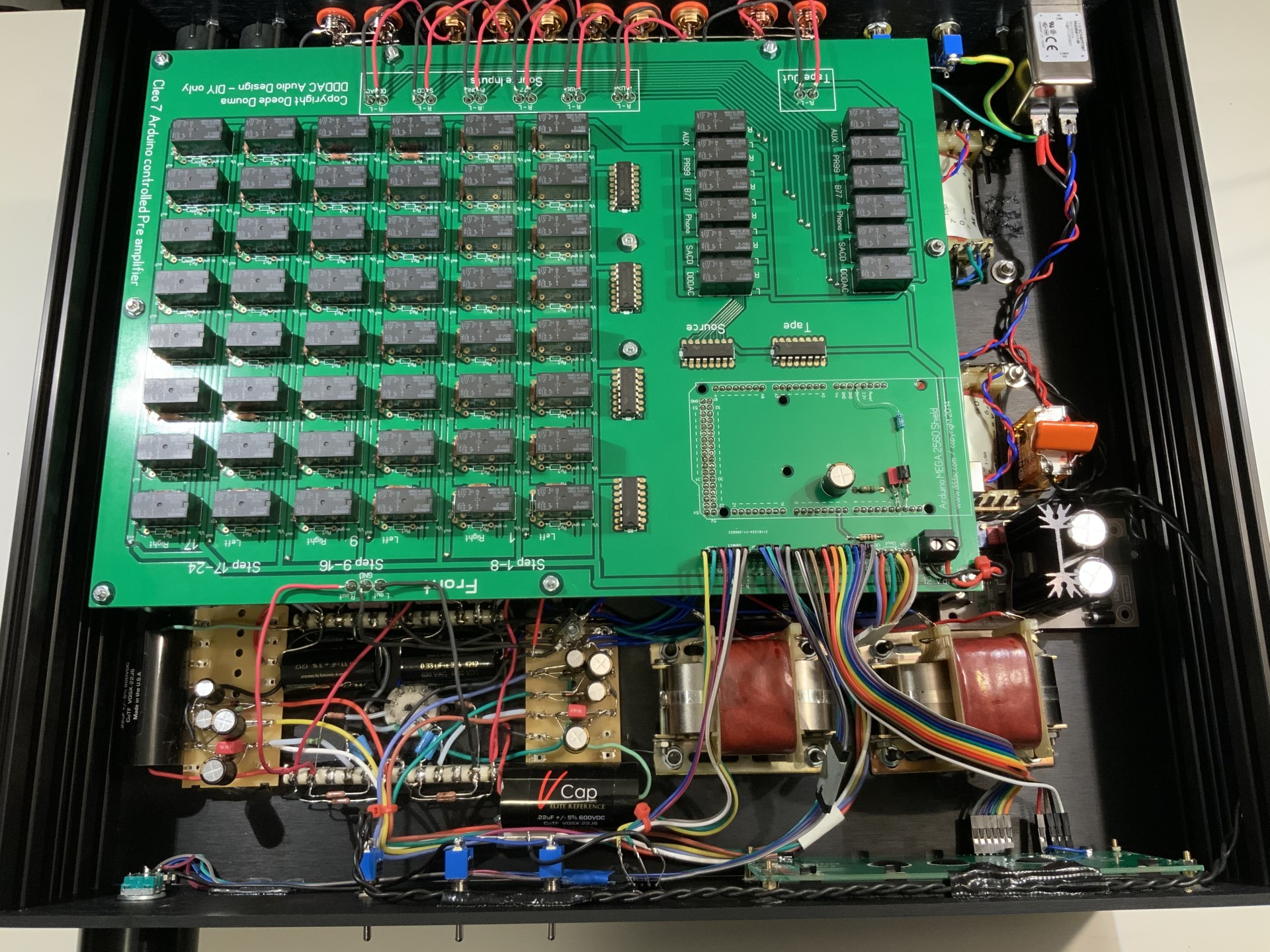
This is how the inside of the CLEO 7 looks like now… Pretty cramped again, but still accessible for measurements and repair. I kept signal and power wiring and sections as much as possible apart. And when wires have to cross at least under an angle and not parallel. A good practice is also twisting the wires to avoid any EMI and RF to induce noise and hum.
UPDATE 2020-10-11
And…. ready !!
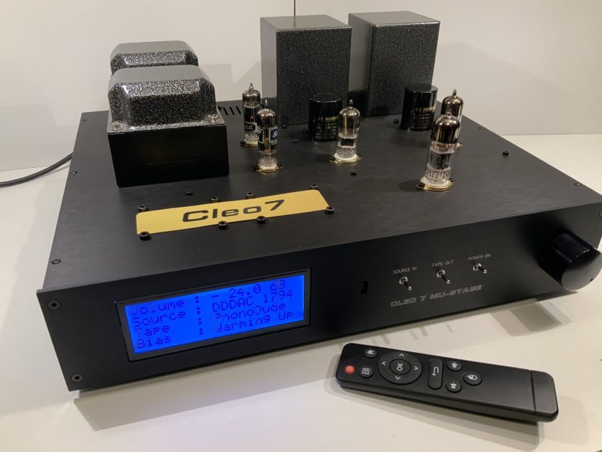
The Cleo 7 is ready 🙂 As said, some debugging of the code, some final checking and powered up without any smoke! This is how it looks right now. The “golden logo” is still paper. I will have a nice aluminum version of course from Schaeffer in Berlin.

The Arduino MEGA allowed me to not only drive a nice LCD display full of information and do the actual control of the IO board. I used the analog inputs to read the three bias voltages (Power supply, Output and Uk) as the amplifier is using up its tubes, I will get a warning to check it and then I will have the exact values and a percentage of the ideal situation.

Cleo 7 LCD Screen 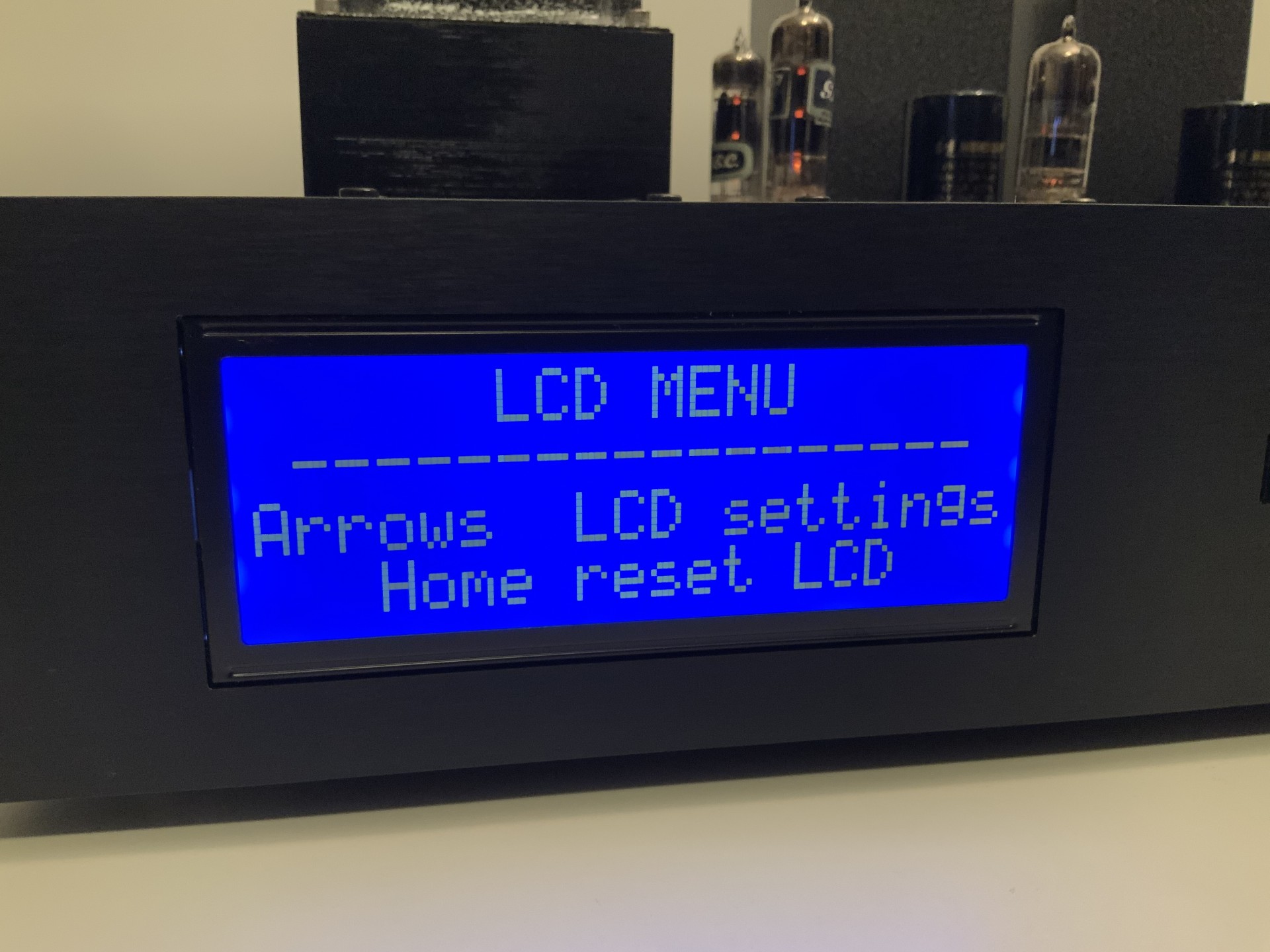
Cleo 7 LCD Screen 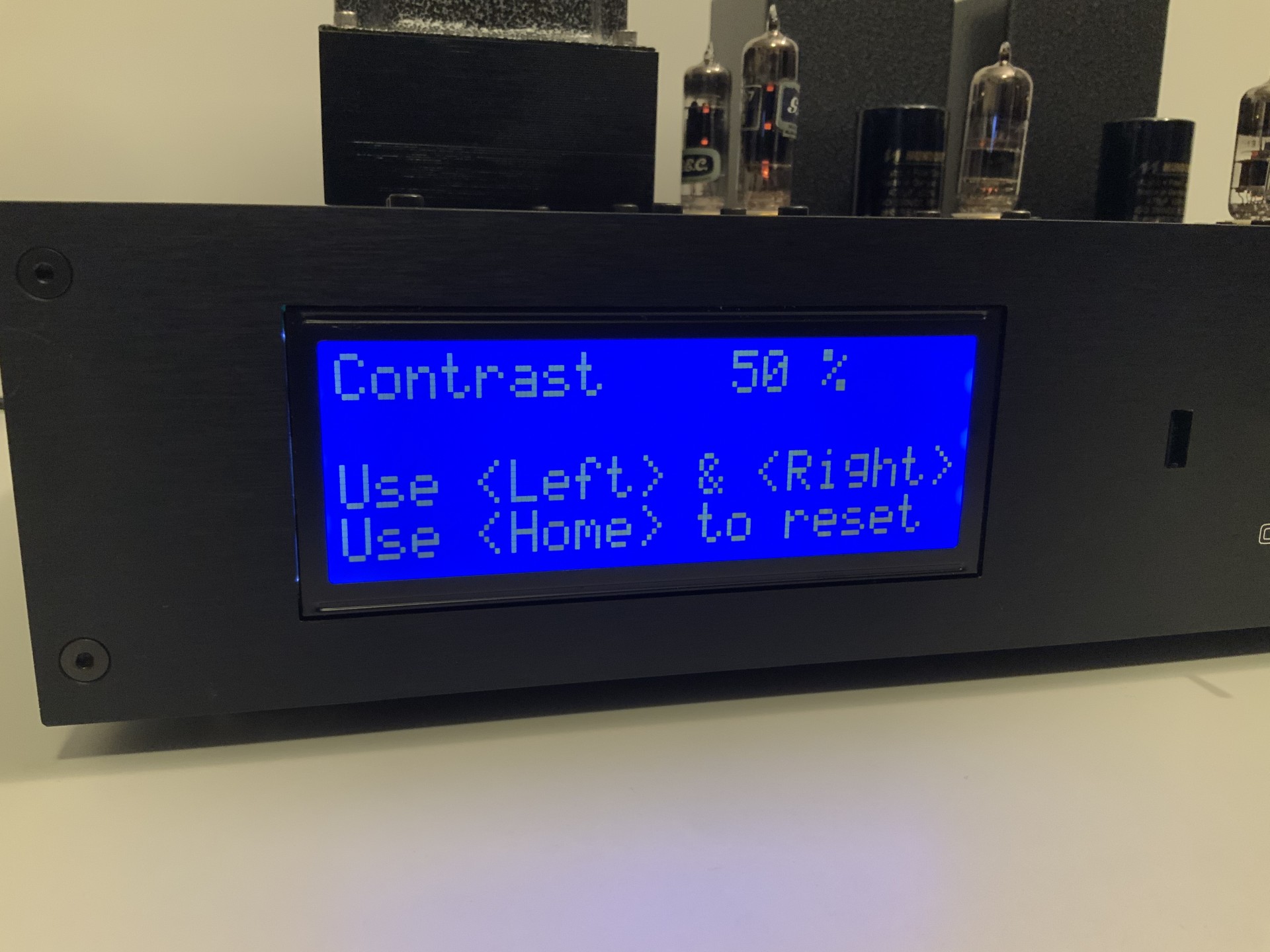
Cleo 7 LCD Screen 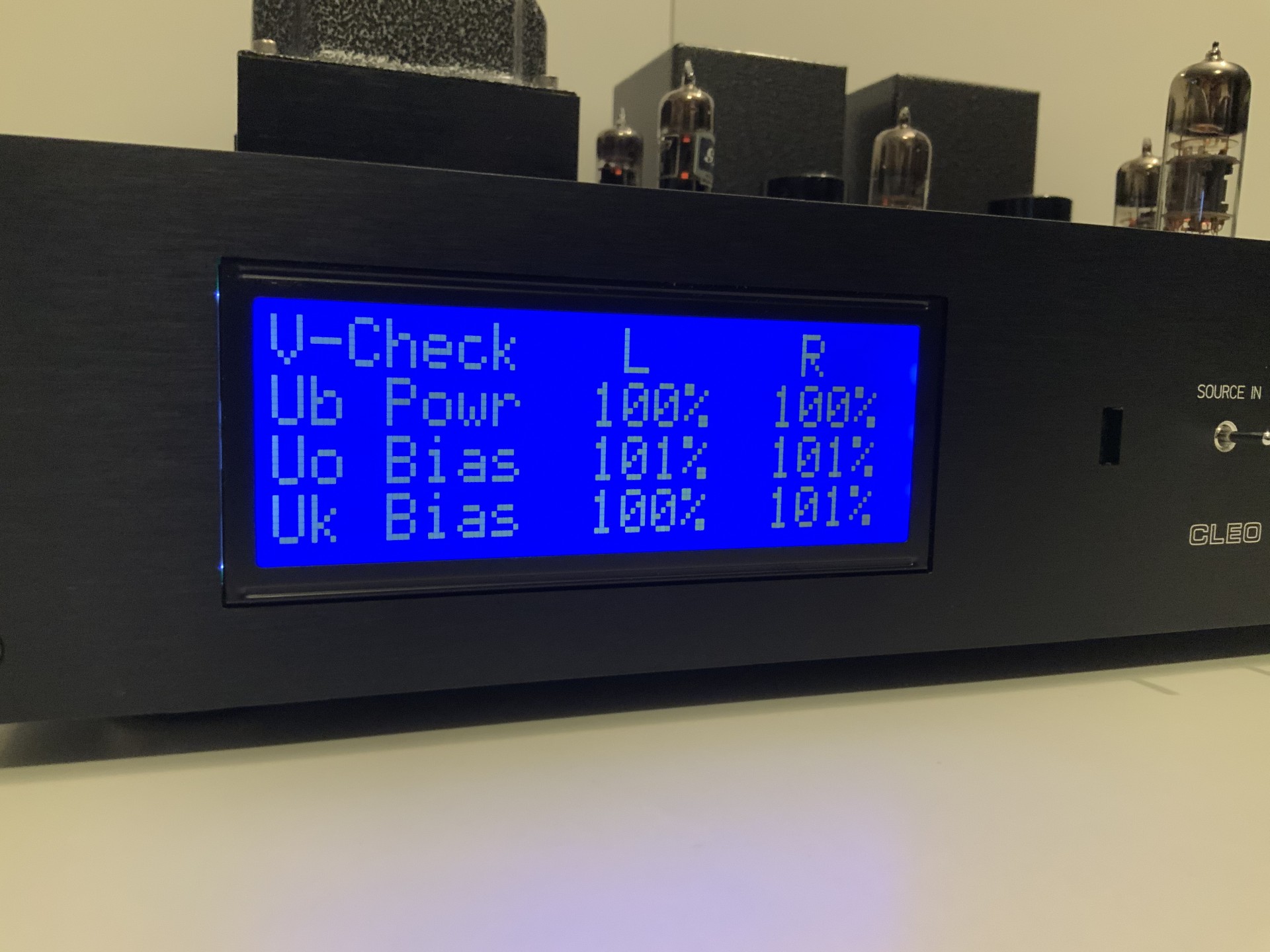
Cleo 7 LCD Screen 
Cleo 7 LCD Screen
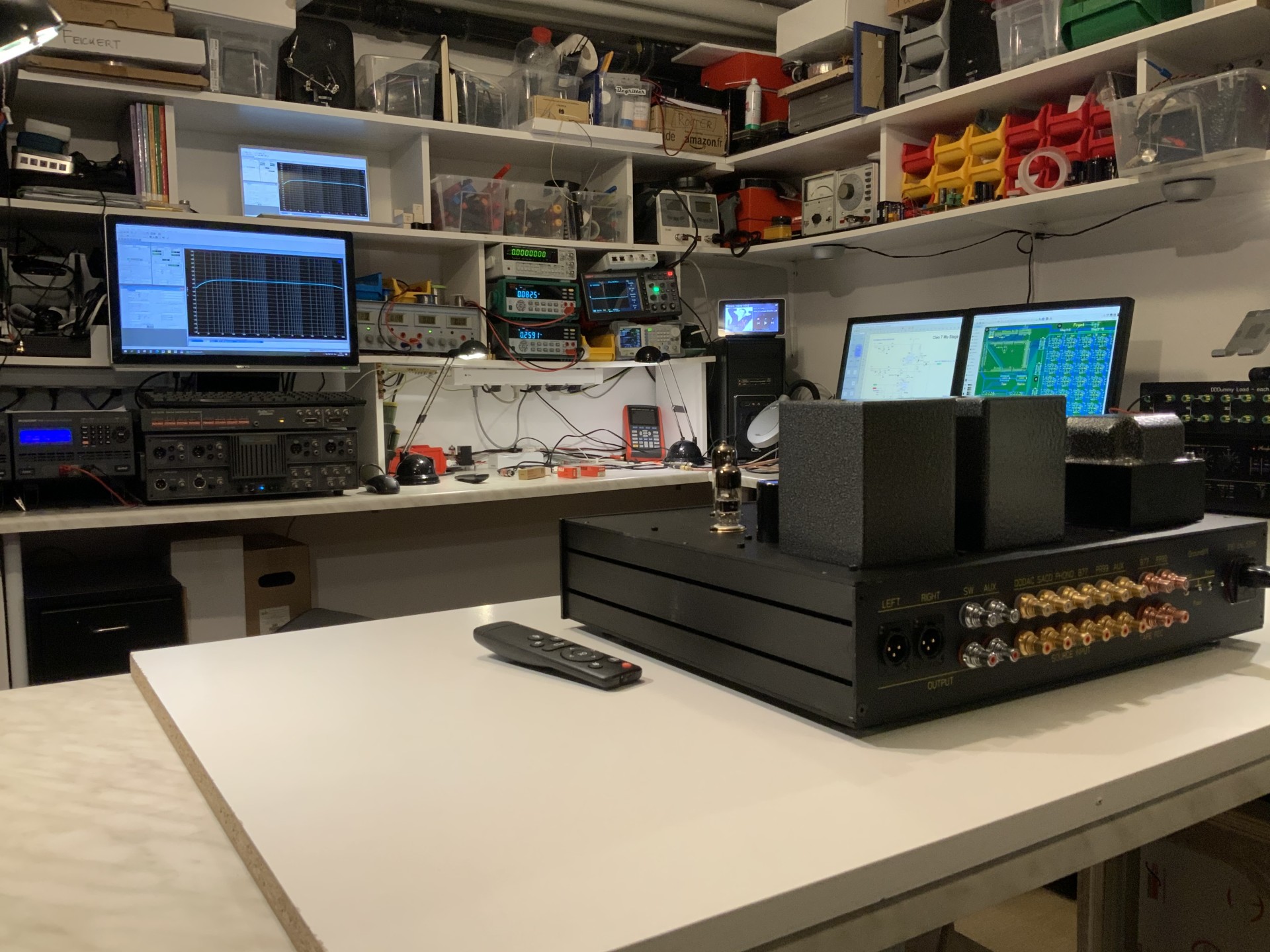
May be nice to show my work shop where it all took place! As you can see, a wide range of good tools to make sure nothing went wrong and it all measures like expected. Of course the music is what counts ….

After some 24 hours burn-in, I was able to listen to the first notes. For the time I was working on the Cleo, I bought an Acoustic Research A-03 on Ebay. A nicely musical sounding amplifier. But now back to Cleo the seventh !!
Final Measurements and listening impression
The final measurements were very close to the preliminary. I now did really L&R channel. Tubes always have some deviation as you see, but nothing serious. I am extremely happy with results. As you can see high bandwidth, extreme voltage output at low distortion and only -109 dB hum versus full output: nicely quiet…

Cleo 7 Gain and Frequency response ( Gain 22.7dB = 13,7) – final 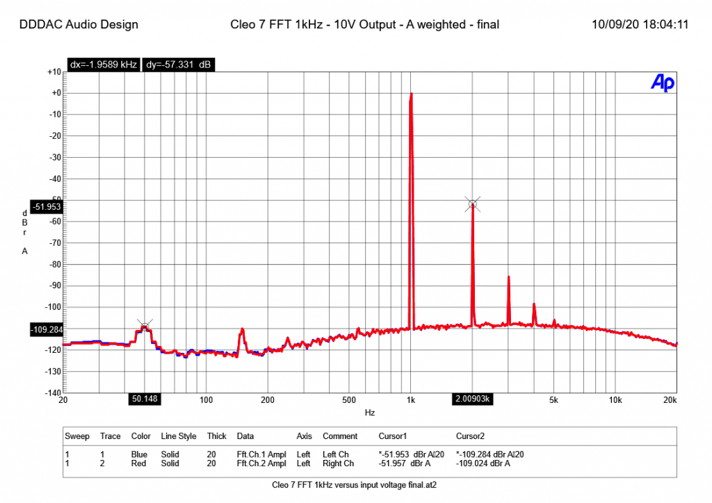
Cleo 7 Gain and Frequency response ( Gain 22.7dB = 13,7) – final 
Cleo 7 THD versus output voltage – 1kHz – A-weighted – final

Listening was a real joy. YES listening with a capital “L”… the first notes already revealed why I have been doing all this. Back to a very detailed open and wide music stage. Especially the texture of voices and musical instruments are phenomenal. This really curls up your toes 🙂 When playing more pop, R&B and alike, it became clear how power full the Cleo 7 plays. Really dynamic and full pressure where impulses kick in. I did not experience any problem at all with, what some claim, “Sagging” when tube rectifiers are used. For me the tube rectifiers are just helping to reveal more micro details. All combined with silky, but still very transient rich high tones, makes this a dream to listen to.
Ergo, I am a happy man, and VERY glad I have my CLEO back. Specially now it has all the functionality I was longing for….
8 thoughts on “Upgrading my CLEO 6 Tube preamplifier to CLEO 7”
Very interested in this project and always wanted to build a tube pre amp 😉
Good luck, enjoy and I will be following your journey Doede!
Good progress Doede and looking great
WELL DONE and looks EXCELLENT !!
No worries 🙂 It won’t be “daily” but for sure regular!
Very nice build with the Arduino. Did you by chance measure the output impedance?
I want to build this but my amps like a low impedance.
Thanks
Hi Ben,
thanks for the feedback. The output impedance is roughly 300 Ohm. But it depends also on the output capacitor. If you really need to go low, add a Ck bypass of 100uF parallel to R11 and increase the output capacitor by paralleling with a 10uF for example. All arbitrary and depending on your personal situation.
you can send me a mail on it if you want
Doede
Doede, can you give more details about the print? Some drawings and layout of the relay volume control would be great.
Hi Jan, I would, but till today I did not made any drawings of the full PCB. In the PDF there is the concept but not the detailed 24 steps and values.
IF I will do this i will publish it of course