The DDDAC Mu-Follower Module

And how PCB capacitance spoiled the fist version…
As you might have read, I am working on designing and building a tape head tube amplifier. For this you need quite some overall gain to overcome the gain losses in the equalization filter. Like at least 200.000; reason to split it up in 3 stages. Now every stage must have following specifications to make this work (with equalization filter in between)
- Gain of minimum 60x per stage (I want triodes for linear behavior)
- High input impedance > 1MOhm (the filter likes little load)
- Low output impedance < 1kOhm (the filter likes low source impedance)
- An output of at least 10V RMS with low THD (<1%) (your ears like this)
- Low noise and hum (of course…)
- Bandwidth of > 50kHz (not easy with triode/high-gain/no feedback)
There are only few triode tubes who will provide such high gains. The likes of ECC83, 6SL6, WE420A and 5755 are the most common ones. I used all of them in my Phonodude designs with excellent audio performance. The downside (as there always is one) from these tubes is the typical high plate resistance. But more on this later
Certainly a proven and excellent way to achieve the above design criteria is the MU Follower. And then I had this idea of making it modular… just design a small PCB with one follower on it, which can be universally used. I already mentioned the tape head amplifier where you need three, but with two modules you could make a RIAA Phono amplifier with a passive RIAA filter between modules or just use one module as a pre amplifier? Of course that is for ONE Channel only….
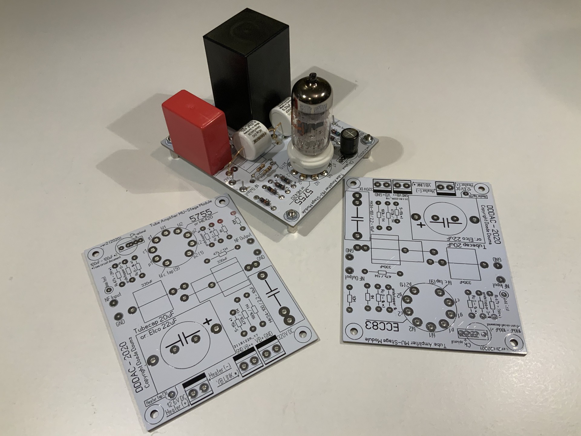
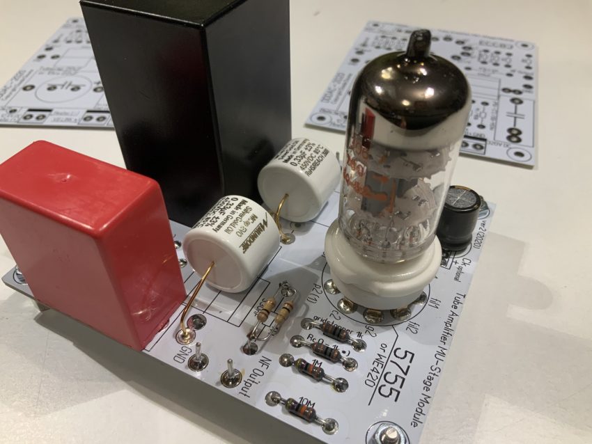
On the picture above you see, that I designed two versions of the PCB: for the 5755 (Mu/gain of 70) which is suitable with very low or no Rk) and the good old ECC83 (Mu/gain of 100). After having already black, blue, green and red PCBs, I decide, for no particular reason at all, to make white ones this time… 😉 They are for universal use and together with the circuits diagram (PDF) – download here – it can be configured easily for several different applications.
Let’s get a bit technical and check the design:
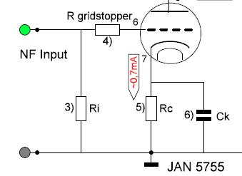
I will not go too deep in the MU follower. There are plenty of good articles when you google this. Just explaining what I did… here is detailed image or download the pdf here …

Let’s follow the signal and start at the input. Depending on whether this is a phono amplifier or for a following stage, you will most likely put 47k or 1M at the Ri position. You should not go too high as the current grid might start playing a role in your bias. Still things will be fine but it should not be overdone… After that the signal will pass a grid stopper. Very arbitrary value – I use 1k…
Below is the cathode Rk resistor which does the auto bias. I am using 1k (coincidence) This will let the tube work in a good linear area. Use the datasheet for this… Again this value is not so critical. it all works fine with zero Ohm up to 2k.
Keep in mind that the Voltage over Rk is the maximum voltage you want to apply as signal input to avoid grid current and high THD distortion when it gets above this. Better stay really below it at least a few hundred mVolt. Let’s see: for a 0dBu output (=1.55V rms) I would need like ~ 20mV input, so a voltage of 0,7 Volt is more than sufficient.
Rk (Rc) can be decoupled with a capacitor. In the Mu Follower it does very little in terms of distortion and total gain – but later there will be more why this is an interesting story after all!
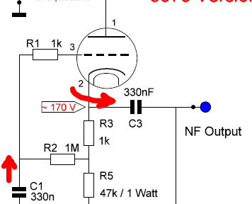
The top tube section is wired up as a source follower and bootstrap for the plate load resistor (R5) of the bottom triode. This results in two good things
- The plate load resistor (R5) is multiplied with the triode Mu so the bottom tubes “sees” like 3-5M Ohm. Solving the biggest issue using ECC83 kind of tubes. They have a high (like 50k up to 200k depending on design) output resistance and the load is normally strongly reducing the gain and linearity
- The output impedance is low (actually ~ 1/S) so like roughly 600 Ohm with these triodes. Which is great if you want to drive high precision filter circuits…
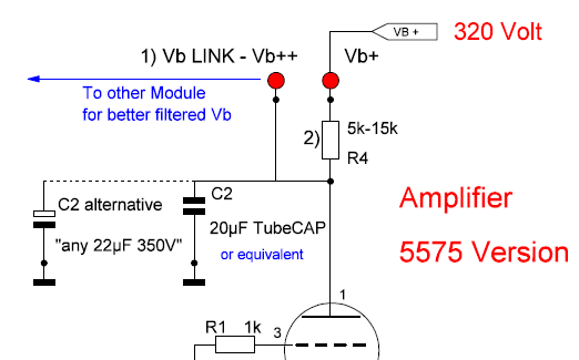
On top of the amplifier tube is a local and simple RC filter for local decoupling and extra power supply filtering. This filtered supply can be re-routed to previous (earlier) modules as they probably work with even lower signal levels. Some extra power supply filtering is than supplied by chaining up the the modules and hence the RC filters.
You see this very often in amplifier designs, also in solid state you see this. It is just good practice
So I received my first drawn PCBs, built one – attached the AP test gear and I was shocked to see that the bandwidth was far lower than expected: -3dB@ 33kHz – bloody hell, what is going on here?
Well… the PCB capacitance caused a very bad mix with the triode output resistance…
So what was the case… The bottom triode has a very high output impedance: (The plate resistance + Mu*Rk = 50k+70k = 120k) Now this output resistance will create a low pass filter with any capacitance behind that. With the 33kHz this would be like 40pF. The top tube has some of course but not so much. OK, it took me while and then I realized I made a classic mistake. Designing PCBs these days is kind of automatically coming with a ground plane at both sides. Consequently, the tracks running at the other side form a capacitor with that. And yes, measuring the bare PCB and calculating it I created a capacitor of roughly 20pF! Seems not much, but this halved the bandwidth…. Back to the drawing board !! I designed the PCB again in a MK2 version. The one in the pictures by the way.
Indeed problem solved as you can see below:
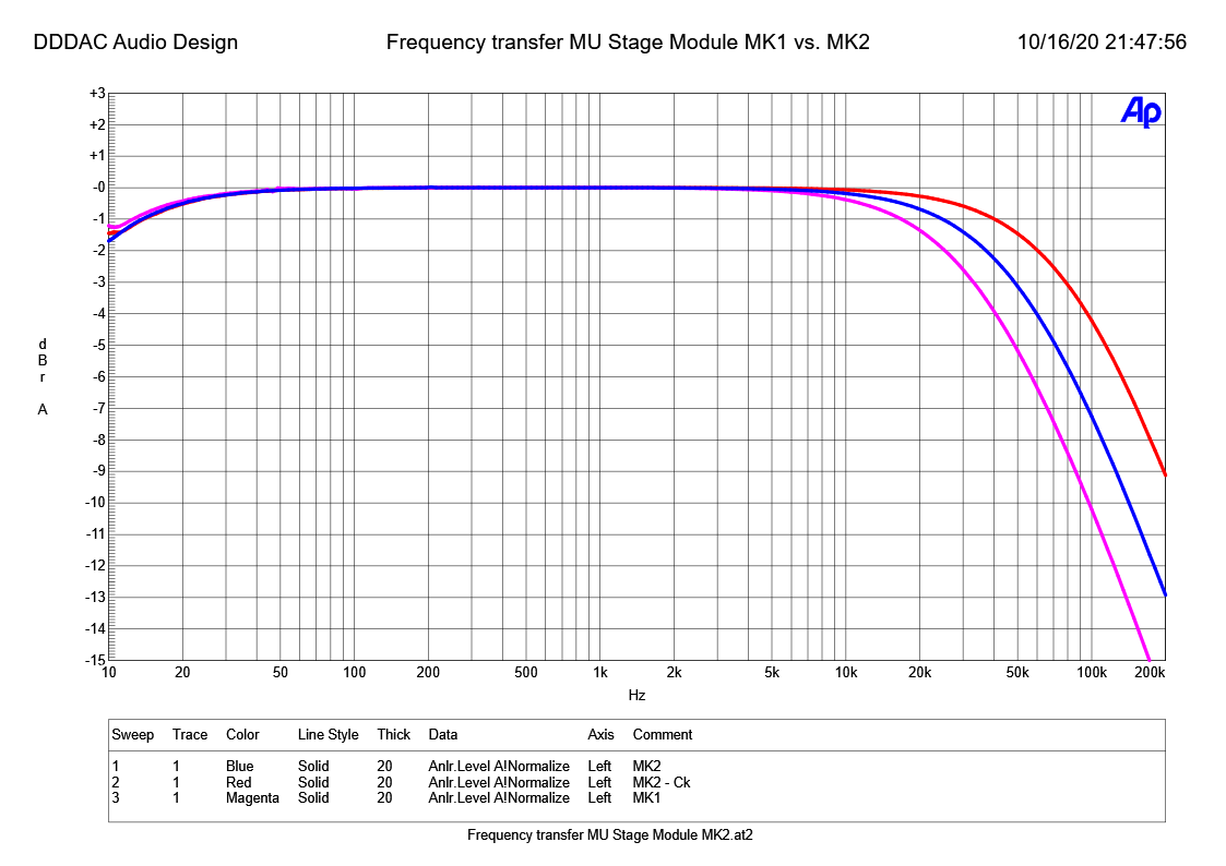
The above measurement graph shows the following:
- Blue curve: the MK2 version (new PCB) with -3dB point @ 50kHz
- Magenta curve: The “old” MK1 version with poor track-routing does only 33kHz at -3dB
- Red curve: when the Rk (Rc) is decoupled the bandwidth increases to 80kHz – here I used the classic way of a large capacitor of 47uF – a “-3dB” point with Rk of 3Hz – This means that from ~ 3Hz the capacitor is the lowest impedance and hence the preferred route for the signal.
So why not just decouple it like that? Well, technically correct, but this capacitors is directly in the signal path. From an audiophile standpoint we typically want to avoid that or use a high quality film capacitor, which is expensive in these values. Again I slept a few nights over it and came with the following lightbulb idea

“What would happen if Ck is only in the signal path (relative to the resistor Rk) at higher frequencies, helping the bandwidth go up, but in most of the audio spectrum, Rk is the preferred route for the music signal ???”
So, this is what happens with various decouple C values:
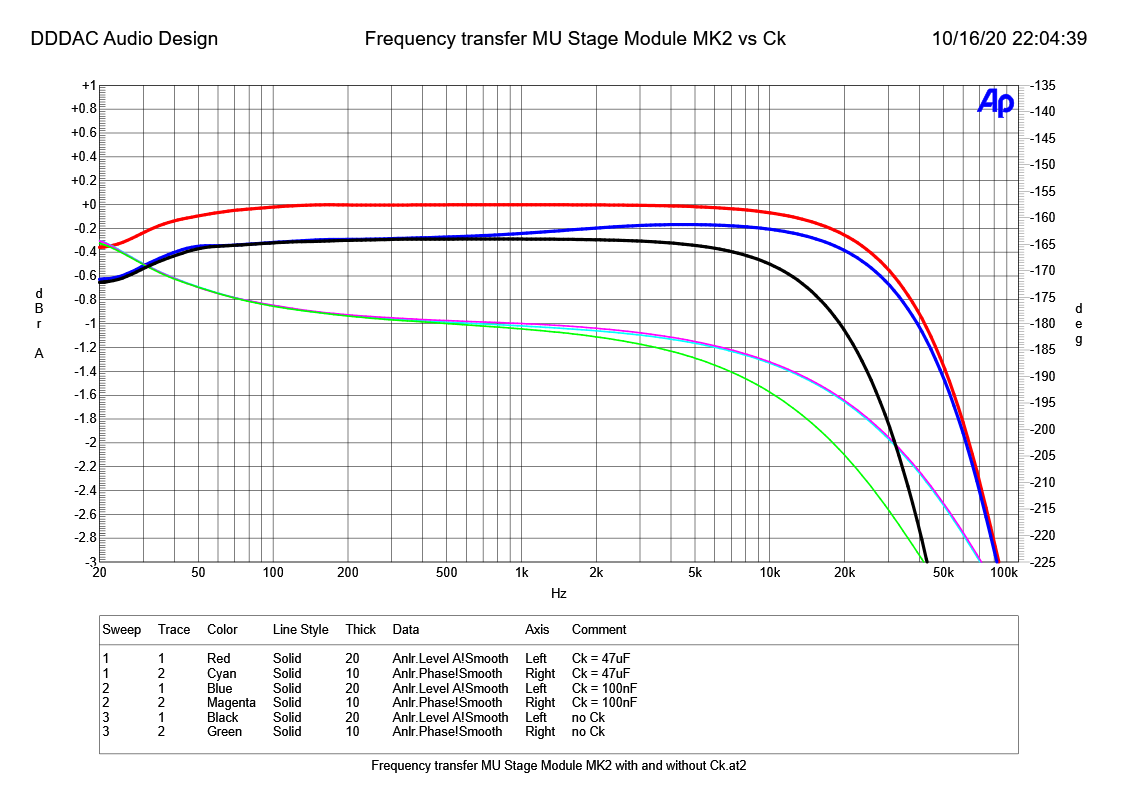
Lets have a closer look to this. The upper traces are the frequency transfer versus 1kHz 0dB level. The ones below are the phase shift of the signal
- Black / Green curve: Starting point with only Resistor Rk in the signal path
- Red / Cyan curve: Here I used the “classic” 47uF capacitor. In a normal resistor loaded triode amplifier this has a large effect on gain logically. NOT in the Mu follower (remember like 3-5Mohm load). The impact is relatively low. The “extra” gain is only 0.3dB. No big advantage for taking the “burden” of an electrolyte in the signal path . Positive is the reduced phase shift, which comes with the higher bandwidth
- Blue / Magenta curve: Here I used a “only 100nF” MKP film capacitor and as you can see the curve starts at the “no-decoupling” point and slowly moves toward the “decoupled” curve” with the higher bandwidth. The phase shift is almost identical with the fully decoupled situation
In conclusion: It is possible to get an almost flat frequency response and a high bandwidth by using a much smaller decouple C as we would typically think / use. The RC value is probably arbitrary as long as it lies roughly in the middle of the audio spectrum. Like I did: 1k * 100nF has a RC value corresponding to 1600 Hz.
Of course the proof need to be in the listening …. but that for later this year
Final Measurements:
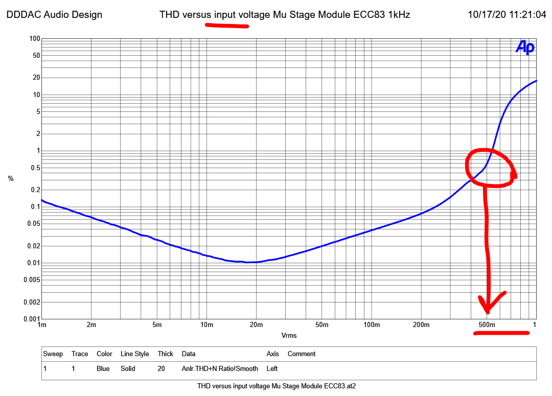
There are some standard measurements I always do to see if the design meets all the requirements – As you can see below it actually does 🙂
Not much to say, right? At 0dBu output only 0.01 % THD. Remember: no negative feedback at all…. straight linear triode behavior. The hammer is you can get like 45 Volt RMS signal out of this nice little module at only 1% THD…. (of course you should not load it below like 100kohm – as in the graph – otherwise there will not be enough current to drive the next stage) Still this could drive a small single ended tube power stage or a TUMOS amplifier for example

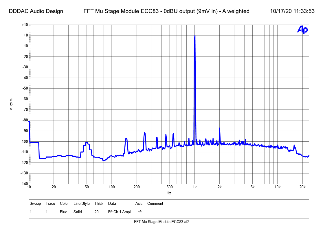
This actually shows the ECC83 version, but the results are very similar between 5755 and ECC83, so I just show this one here.
Looking at the spectrum below, at more normal conditions of a signal output level of 0dBu, we see a weighted hum of ~ -100dB and a very small second harmonic (d2) of only -87dB, which equally 0,0045%. and do not forget this is all with a gain of almost 100 and no negative feedback!!
Conclusions:
I am very pleased with the result. All major design criteria were easily met. The DDDAC Mu Follower has become a high bandwidth, low distortion, quiet amplifier module with huge headroom and good drive capabilities (low output impedance)
On top, VERY easy to build and construct complete amplifiers with the multi purpose PCB. This module will be used in the upcoming tape head amplifier I am working on….
to be cont’d on another post !
2 thoughts on “The DDDAC Mu-Follower Module”
Doede,you are THE MASTER !!