The new DDDAC1794MK3 (DAC and PSU)
Introduction
I spent most of the past year working on a follow-up for the good old (10 years) DDDAC1794-PBT. I promised this would be available for DIY as well and here it is! An introduction story for the DAC and for the Dual Power Supply which is designed to go together with the DAC Board.
Why a new revision? The previous DAC model, the DDDAC1794PBT, was 10 years old. During lifetime, I received a lot of feedback from the DIY community with tweaks, ideas for use or implementation of other parts etc. Also, during that time, I gained a better understanding of PCB design, digital signal routing and analog power supply impedance and noise generation. Time to start thinking on a new version…

As for the Power Supply, it became clear, that it needed to be more modular to be able to use different styles and sizes of mains transformers.
Also, after many experiments and feedback from users of MOSFET rectifiers, it was clear: electronic rectifying was the way to go. I decided to embed the LT4320 and MOSFETs instead of diodes.
Last but not least, for ease of building, I have been using some more SMD parts, so easier to build for DIY.
Another, not unimportant chain of events, was that during Covid 19, the supply chain and availability of parts was a disaster. It made keeping the DDDAC available and alive very difficult. Some critical parts went end of life as well. All those things together made me decide to make a new revision where all inputs, experience, new ideas and learnings were incorporated. I built several prototypes and did a lot of testing and listening, before I believed the final version was ready for DIY 😊
I made some detailed construction and user-manuals
Last update: 22 April 2024 (Smalle errors fixed, Disclaimer updated and few extra info’s)
Current version v1.4 for the PSU and 1.5 for the DAC
(future updates: only here you can download up-to-date versions)
DAC Manual
PSU Manual
The manuals are also supplying more detailed information on how to install the board, connections, settings, bias adjustment etc etc. This will not be in the post below, to keep the post high level introduction. If you are interested in more detail, the manuals are certainly worth reading as well!
Design Goals & Features – DAC PCB
The design goals were not carved in stone and to be honest there were 3 prototype versions where I added new ideas as I went. Below is what the Final version is about (First introduction with v2.6)
- Fully based on the previous DDDAC1794 concept & design (No digital Filtering etc.)
- 4 Layer Gold Plated PCB for optimum signal routing and low impedance power / ground planes.
- Digital section with modern high-speed CMOS Logic.
- Independent MCK digital signal line (still BCK signal) with a one gate Buffer for optimum and low jitter clocking of the PCM1794 ICs.
- Design with 4x PCM1794 DACs on one single board – equivalent to old style two-decks.
- Selected capacitors for every specific function, based research and long year experience and feedback from the user community of the previous DDDAC1794 series.
- Two channels A&B with both 2 DAC ICs in parallel mode (like previous 2-deck DDDAC1794).
- Each channel can be assigned to be a Left and or Right analogue signal.
- The two channels on the board can be paralleled again for “one channel – Mono” mode (when using two mono boards you get like the old 4-deck equivalent)
- Pin-Header and UF/L inputs and outputs (for daisy chaining multiple boards).
- On-board low 1/f noise voltage regulation, separated for digital and analog section.
- Output terminals of 3.3V and 8V regulated power for external applications or tests.
- More pre-assembled, on-board SMD parts for better performance and easier DIY construction.
In regard to paralleling more than two mono assigned boards… in fact it is possible, you can daisy chain more boards and parallel the analogue outputs. If this is useful is unknown, as I did not test it sound wise.
I also recommended for the previous version to stop at 4 decks. Very few went beyond that because they just were intrigued and tried it. It does improve the sound as reported, but is it worth the extra cost? I think no, but some went for “cost no object”. After all it is a hobby….

Specifications for the DAC
| Digital Input | I2S only. Inputs are 3.3V – 5V logic level compliant |
| Digital Input | I2S up to 384kHz / 24bits |
| Analog Output | ~1.2Vrms single ended (two times) or ~2.4Vrms balanced (FS0dB) |
| Output impedance | ~68 Ohm in Stereo Mode and ~34 Ohm in Mono mode. |
| Digital Power Input | 4.0 Volt (~10-50mA) |
| Analog Power Input | 9.0 Volt (~ 200mA) |
| Digital Power output | Regulated 3.3 Volt (recommended < 150mA) |
| Analog Power output | Regulated 8.0 Volt (recommended < 100mA) |
Board Layout and Dimensions
| Board size | 130mm x 180mm |
| Mounting holes spacing | 120mm x 170mm / Dia. 3.5mm |

The DAC PCB and Kit for DIY (through hole parts)
If you would decide to build this DAC, this is what you will find in the full DAC kit:
- PCB with all SMD-Parts already assembled.
- Plastic bag with all the through hole parts and other assembly material.
- For the actual kit the correspondent part list – the part list may differ in future versions, depending on availability of certain parts.
Just check the Audio Creative Web-Shop

Design Goals & Features – Dual Power Supply
Also these design goals were not carved in stone. Two prototype versions were built. Below is what the Final version is about (First introduction with v2.5)
- Based on the previous DDDAC1794 PSU design.
- Audiophile electronic MOSFET rectifying with the famous LT4320.
- Selected capacitors for specific functions, based on research and long year experience and feedback from the user community of the previous DDDAC1794 series.
- Two separate PSU-Units on a single board, which can be physically separated for single board use thanks to easy to use break off points.
- Two output terminals with variable voltage setting (roughly between 3 and of 15V regulated power).
- Two terminals for connecting an optional choke to change filtering from RCRC to RCLC.
- More pre-assembled, on-board SMD parts for higher performance and easier DIY construction.
Specifications for the PSU per unit
| AC Input | 7Vac – 15Vac (for DDDAC1794MK3 recommended use: 2x12Vac) |
| DC Output | Adjustable 3Vdc – 15Vdc (15VAC needed) |
| Maximum Current | 0,4A for use with two DDDAC Boards and 2x12Vac More when care is taken: There is a larger heatsinks needed and possibly lower AC input voltage – read also “Important Note” further below |
| Choke Option | Recommend 1H with max 4Ohm for DDDAC1794MK3 use |
Board Layout and Dimensions
| Board size | 130mm x 130mm |
| Mounting hole spacing | 120mm x 120mm / Dia. 3.5mm |

Important Note and Warning:
If the power supply will be used for applications other than powering the DDDAC1794 MK3, replace the 0.22 Ohm resistor R11 and R14 with a wire bridge.
The PSU PCB and Kit for DIY (through hole parts)
If you decide to build this, this is what you will find in the full kit:
- PCB with all SMD-Parts already assembled.
- Two heatsinks. (Size is intended for use with two DDDAC1704 MK3 boards.)
- Plastic bag with all the through hole parts and other assembly material.
- For the actual kit the corresponding part list – (the part list may differ in futures versions, depending on availability of certain parts.
Just check the Audio Creative Web-Shop

Mains-Transformer Suggestions
There are two options: two independent transformers with single secondary winding or one transformer with two separated secondary windings.
Do NOT use windings with center tap!! This will not work properly.
In my own setup, I am using a 50VA transformer with two 12Vac separated secondary windings.
I suggest a minimum 50VA Transformer for optimum compromise between headroom and
cost. Bigger is “better” but also more expensive. Try for yourself if it is really “better”.
Even if a 15VA transformer will work fine, I would not use those small ones, as they are more prone to large output voltage deviations under different (no) load conditions.
The AC voltage of the transformer should stay under 15 Vac for proper operation.
Measurements
I know, some might say “I only measure with my ears!” Yes, fine, I do that as well, but that is more like “reviewing & evaluating”. I always measure everything I design, in depth. I need to be 100% sure, the electrical specifications and behavior of the design is beyond doubt! I also want to understand if my design choices have lead to the expected results. Only then, when I am satisfied, I can lay back and start listening.
So let’s first check the measurement results for the PSU.

For the on-board regulation, there are a few things to consider. Noise generated and output impedance of the regulator. The lower the output impedance, the better digital residues on the power plane will be dampened. Decoupling of the analogue signals will work better. I have been looking for lowest possible impedance at lower frequencies (insider tips I got for an out of the box implementation with the LT1763). The below 2 mOhm is the best I could achieve in several experiments.
At the right there is a comparison of some commonly used other regulators. I think it speaks for itself. The little bump is no big deal I believe, probably could have been lower by adding more and bigger capacitors on board… but as some point enough should be enough.


Understandably, the regulator should not generate too much noise by itself. At the left is a very busy chart, so take your time. It is a comparison of some selected other regulators. Note, that the 8V on-board regulator test is not 100% fair. All others were tested with a resistive load. The 8V on-board regulator, is in a live application with the PCM circuits. I know from experience that this causes more noise. Anyway, I am happy with the results!
Last measurement, to show the difference between an early prototype where the only difference with the final power supply, is the MOSFET rectifying versus Diode rectifying.
If this is the sole reason it sounds better, hard to say, but for a change, there is a clear difference between both versions.

Let’s have a look at the most important results for the DAC:

No surprise, NOS / No-Filter DACs with passive I/V and high-level output, tend to have higher THD than data sheet implementations with high feedback opamp circuits. Point is to keep it low enough…
As I am not looking for 0,0001%, but for the best sound, I have compromised for sufficient low THD% at high level output. Mission completed as you see at the right:
The dominating distortion d2 in single ended is only 0,1% – no one will be able to hear this. Your speakers will produce much more and most music is well below 0dB Full Scale signal level anyway.
For the balanced output things are better of course as d2 is mostly cancelled out. Only d3 stays dominant at, again, only 0,03%.
The better the linearity, the more low-level details you will hear in a DAC. The linearity of the MK3 is the best I have seen in all my DACs so far. As you can see, even up to 23 bits the conversion is almost a straight line with only small deviation at the end of max 1dB. Only in the last two bits there are small deviations from the theoretically correct value.

From a DAC you expect a straight line in terms of frequency response. Without a coupling capacitor or OPT, that is the case of course. See the graph below. The balanced output is, no surprise, 6dB (double) more than the single ended output. Values are absolute in dBV (in real Volt you get: ~1,2V and ~2,4V)

The more interesting curve is the one with the DDDAC specified Sowter OPT. Even with one board (like a two-deck “old DAC”), the 3dB cut-off frequency @23Hz is sufficient for most audio systems. A board in mono mode will half that frequency and you will add 3dB Bass in the very lowest octave.
Honestly, for a NOS DAC with passive I/V, these results are remarkably good. Better than the previous ones. These are solid results, supporting the listening results, which were also exceeding my expectations.
OK, I am indeed satisfied now. Enough technology and background, how does it sound?
Test Setup for the listening-review
The listening review had three goals. First, to listen in general and compare with the “old” DAC. Secondly, I tried two versions. One with Nichicon UKA and one with RR7 Polymer capacitors in the analog section. Number three to check if the choke was still making such a significant difference.
I strongly believe you need to be able to switch back and forward, while listening, between different alternatives, to be really able to come to conclusions. Real A-B comparison so to speak. Going blind is even better – when possible.
I am using my “Bluetooth Relay-Switch-Unit” for that. From the listening position I can select (with my iPhone) position A or B. If you do not “look and remember” what you actually connected to A and B, the test gets more honest and “blind”.

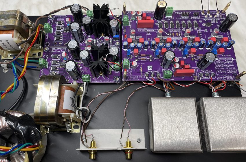
This was my Test Setup:
- 50VA Transformer with 2x 12V sec.
- DDDAC Dual Power Supply
- Both sides having the DDDAC AE Choke option connected – from AE Electric – Link to Website –
- Two DAC boards in stereo mode. One with the UKA capacitors and one with RR7 Polymer versions
- DDDAC specified Sowter Output Transformers (OPT)

I2S coming from my workshop streamer with:
- RPI-3B with Ropieee (running on Roon)
- Ian Canada FiFoPi Q2 with Accusilicon 338 clocks
- Tent Shunt at the clean side of FiFoPi
The inputs from the two Sowter Output Transformers are switched between the balanced (POS & NEG) outputs of the two DAC boards. Each board is running in stereo mode.
I deliberately did NOT notice which position of the switch board was connected to which DAC version. So, this has been one of those TRUE “blind” Tests.

Listening
General impressions versus the “old” DDDAC
This is not a 100% one on one comparison, as the setups are not 100% the same, but they are comparable enough.
I have been listening to all kinds of music, Classic, Pop, “High-End” stuff etc. At the end the outcome was always consistent. Sometimes less, sometime more obvious.
Spoiler, the differences are not world shocking. Nevertheless, I could hear the fruits of all the efforts to implement all described above. There is increased ease of listening. That extra touch of naturalism. Small details & texture have improved. SSSs are softer and natural. Focus is sharp. I must admit, part of this is also thanks to the choke option. My reference DAC has also CLC filtering. The cooperation between all elements in the MK3 system, is just very harmonic.
Specific impressions on two different capacitor options in the analog section
To recap, (nice pun), the only differences between the two boards I listened to, were the 16 capacitors in the analog section. I was just very curious on the effect with different capacitors. I used:
- Nichicon UKA series (Audio grade: Selected materials to create superior acoustic sound)
- Nichicon RR7 series (Ultra low ESR and Impedance, even at high frequencies)
The outcome was pretty clear. The UKA capacitors sound (as far as my ears are concerned…) dynamic, detailed and offer a very spatial soundstage. Bass is punchy and voices are pinpoint. More in the back of the sound stage than forward like with the RR7.
The RR7 capacitors offer a more forward sound, larger voices and instruments. Total sound is more laid back and kind of warm. Bass is more prone, rounder and thicker, soundstage is still open and clear.
As I will be asked anyway: My personal preference is to use the Nichicon UKA. This is the reason they are also in the kit.
Now, IF (!) your personal preference, or the simple need to adapt to rest of the audio system, would want you to rather have the polymers (kind of “Englisch” sound”) installed in your DAC, just send me an E-Mail. I still have some and could send you a set. I will charge you just the cost of parts and shipment… Offer lasts as long as I have some sets left.
Again, chokes

To make 100% sure, I also changed the Choke in the analog section (which has most impact) from Choke to no Choke (hard wire). The result was in line with my earlier tests. Soundstage shrinks and is less detailed, less air in between everything. I repeat, a Choke is a must tweak option.
I also had a “monster Choke” sent to me by Ed, just to try for fun and see if “Bigger is also Better”. Small screwdriver for scale… It was a Lundahl LL2771 in parallel mode. Well, BIGGER is not per se better. In fact, the amorphe DDDAC AE Choke still offers this precise kind of sound stage and low-level detail. The BIG Lundahl sounded the same as the LL2733 one in my earlier tests. But… much closer to the Amorphe one. I must say, BASS punch was a tad more impressive with the big one. But it just does not sound so natural… The amorphe ones stay…

Conclusions
- Design goals were all met, which is nice 🙂
- The sound print of the MK3 is the same as the old DAC, very analogue, very open and detailed.
- Do not expect “unbelievable”, “my jaw dropped”, “I could not listen to the old one anymore” kind of differences. The old one was not that bad, LOL – I categorize this as “worthy improvement” absolutely worth all the effort.
- The MOSFET rectifying paid off.
- Again, in the final versions, the use of the Choke was clearly an eye opener. In fact it is a “must-tweak”
- The DAC & PSU are, also thanks to the easier setup (more SMD), very nice and rewarding DIY-Projects!
In summary, it has been great fun to put the whole project “DDDAC” upside down and inside out. I very much like the results and honestly, I would not know what to do next to further improve. For this, experience showed, that feedback from the DIY community, from people who actually built the DAC, has always lead to new ideas and improvements.
Ergo, start building, tweaking, experimenting and enjoy the music. Because that is still what this was all about.
If you are interested after all this reading and you want to build this DAC, Audio Creative is the exclusive global dealer for the DAC and PSU kits. Just check their Web-Shop If you will.
Useful Links related to this Post
AE Electric Website for the DDDAC Choke – use contact button to ask for price and delivery time.
Audio Creative Webshop for the DDDAC Kits
Link to DIY Audio Forum with the “old Dac”
Link to Technical and Support Thread for the MK3 series on DIY Audio Forum
Link to Swap Meat on DIY Audio Forum where I offer clearance sales
.
24 thoughts on “The new DDDAC1794MK3 (DAC and PSU)”
A good morning to you Doede,
Congratulations with the birth of the MKIII 1794 NOS DDDAC 🥳
I know that you’ve been busy with the development of it and now the time has come to show it to the rest of the global audio community.
No doubt it’ll have a strong following with DIY’ers who will try to get more out of it, but that’s what this hobby is all about.
Cheers, Paulus
Spot on Paulus, thanks for the supporting words.
Groetjes
Doede
Hello Doede,
Congrats on the birth of your next brainchild. Will you publish the schematics. I’m hoping to incorporate some ideas in the old DDDac.
Regards,
John
Hi John,
There are no secret things in the whole setup.
Yes I will be providing them at some stage. It is just a lot of work to rework the old drawings…
Great. Take your time. It’s a hobby not work.
Goodday Doede, a great job you’ve delivered again!
I have a Question, as I understand it well, I can use the new psu with a dual tap 15V transformer for the MK2 with four dacboards with 12/5 volt out and when I build the MK3 I only have to lower the voltage with the trim potentiometers into 9/4 volt?
And I have for the FiFoPi 3,3V in a class D LDOVR with a R 165 ohm C47 uF attached, do I have to change any value here if I lower the 12 volt to 9 volt ?
Kind regards,
Martin.
Thanks Martin,
First question: simple yes, that is correct…. BUT… you need to use the larger version (50mm high in stead of 38mm) of the heatsink at the 12V side of things. when you order, ask Dick or Marco if they can put one 50mm heatsink in the kit.
What current will you draw from the 5V side? if it is significant, you need also a larger heatsink or you need to reduce the AC voltage at the input (different transformer or power resistor) – let me know, so I can help
Second question, yes, you must lower the R as the voltage drop is reduced. My best guess is like 82 to 100 Ohm….
best regards,
Doede
Thank you for the quick response and I’ll come back to you when I have more things to solve.
kind regards,
Martin.
Hello Doede,
For now I’m gonna replace the old red psu with choke for the new one with choke, setting them on 12v and 5v for the MK2 DDDAC.
On the red psu I had also replaced the C3 into a 22000uF type, Is it wise to replace the C1 and C4 for 22000uF or maybe C1,2,3, and 4 for 22000F on the new psu too for same effect
Kind regards,
Martin.
Hi Martin,
Yes you can, but if the difference is significant is hard to say. But, bigger is “better” in this case so give it a try 🙂
Hello Doede,
I would be interested in building this DAC.
my question is whether it is possible to buy the PCB or the Gerber file with the Bom list.
I would love to buy it.
Best Regards
Strácz András
Thanks for your interest Strack. The only way to finance expensive developments like this, is to sell kits afterwards. By only selling the PCB this would never been able. So the answer is unfortunately no. I hope you still will be interested and ready to support developments like this by actually buying a kit.
Kind regards
Doede
Hi Doede. Would 4.3V and 9.1V be suitable for the input?
Sure no problem….
Thanks for replying.
One more thing, do paralleling boards reduce THD?
No ist does not, but the jitter is reduced and output impedance is two times lower. Also it offers the opportunity to make completely double mono setup.
Hey Doede. What do you think of adding a tube output stage to the DAC like this one: http://www.audiodesignguide.com/DAC_Output/index2.html
Hi Justin, basically what you show here is a balanced amplifier with a tube and mosfet voltage follower. Nothing wrong with it.
There is no need for this if you already have an amplifier you like of course. The DAC board already has a high output and low output impedance.
From the circuit it is hard to say if it sounds great. Looking at the whole circuit, I suspect it is not specifically high end ? So need to try if it is an improvement over what you have now I guess.
Hi Doede. Will either of these chokes be ok for the PSU?
https://edcorusa.com/products/xc100-1h-500ma-1h-500ma-choke
https://www.hammfg.com/part/193S
They both are 1H but have higher resistance and current.
Hi Justin,
i think they are both too high in resistance. And the price is not so far away from the AE ones with the amorphe core. With that core sound is really better
Hi Doede. I got an idea that paralleling two chokes will halve the resistance. The edcor ones are $56 each.
Hi Doede. Do the output transformers from Audio Creative perform similar to Sowter ones?
I cannot tell, as i never had them next to each other. I use the Sowter ones for their dynamic and detailed sound. For all bass reproduction is very tight